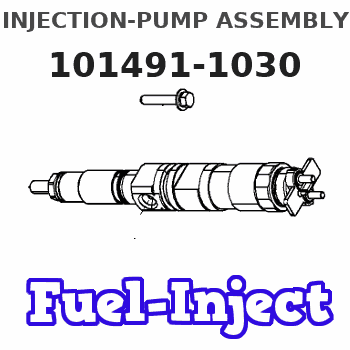
Information injection-pump assembly
ZEXEL
101491-1030
1014911030
MITSUBISHI
ME016096
me016096
Rating:
Cross reference number
ZEXEL
101491-1030
1014911030
MITSUBISHI
ME016096
me016096
Zexel num
Bosch num
Firm num
Name
Calibration Data:
Adjustment conditions
Test oil
1404 Test oil ISO4113 or {SAEJ967d}
1404 Test oil ISO4113 or {SAEJ967d}
Test oil temperature
degC
40
40
45
Nozzle and nozzle holder
105780-8140
Bosch type code
EF8511/9A
Nozzle
105780-0000
Bosch type code
DN12SD12T
Nozzle holder
105780-2080
Bosch type code
EF8511/9
Opening pressure
MPa
17.2
Opening pressure
kgf/cm2
175
Injection pipe
Outer diameter - inner diameter - length (mm) mm 6-2-600
Outer diameter - inner diameter - length (mm) mm 6-2-600
Overflow valve
131424-5620
Overflow valve opening pressure
kPa
157
123
191
Overflow valve opening pressure
kgf/cm2
1.6
1.25
1.95
Tester oil delivery pressure
kPa
157
157
157
Tester oil delivery pressure
kgf/cm2
1.6
1.6
1.6
Direction of rotation (viewed from drive side)
Right R
Right R
Injection timing adjustment
Direction of rotation (viewed from drive side)
Right R
Right R
Injection order
1-3-4-2
Pre-stroke
mm
3.5
3.45
3.55
Beginning of injection position
Drive side NO.1
Drive side NO.1
Difference between angles 1
Cal 1-3 deg. 90 89.5 90.5
Cal 1-3 deg. 90 89.5 90.5
Difference between angles 2
Cal 1-4 deg. 180 179.5 180.5
Cal 1-4 deg. 180 179.5 180.5
Difference between angles 3
Cyl.1-2 deg. 270 269.5 270.5
Cyl.1-2 deg. 270 269.5 270.5
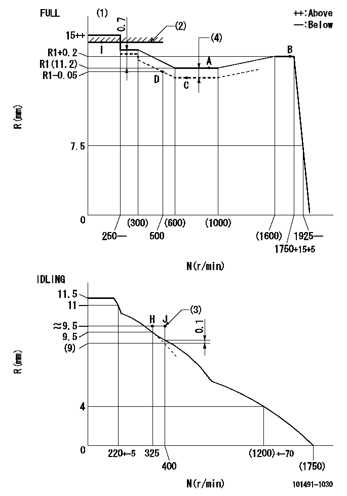
Injection quantity adjustment
Adjusting point
-
Rack position
11.2
Pump speed
r/min
900
900
900
Average injection quantity
mm3/st.
59.5
58.5
60.5
Max. variation between cylinders
%
0
-2.5
2.5
Basic
*
Fixing the rack
*
Standard for adjustment of the maximum variation between cylinders
*
Injection quantity adjustment_02
Adjusting point
H
Rack position
9.7
Pump speed
r/min
325
325
325
Average injection quantity
mm3/st.
10
8.7
11.3
Max. variation between cylinders
%
0
-10
10
Fixing the rack
*
Standard for adjustment of the maximum variation between cylinders
*
Remarks
Adjust only variation between cylinders; adjust governor according to governor specifications.
Adjust only variation between cylinders; adjust governor according to governor specifications.
Injection quantity adjustment_03
Adjusting point
A
Rack position
R1(11.2)
Pump speed
r/min
900
900
900
Average injection quantity
mm3/st.
59.5
58.5
60.5
Fixing the lever
*
Boost pressure
kPa
44
44
Boost pressure
mmHg
330
330
Injection quantity adjustment_04
Adjusting point
B
Rack position
R1+0.2
Pump speed
r/min
1750
1750
1750
Average injection quantity
mm3/st.
69
65
73
Fixing the lever
*
Boost pressure
kPa
44
44
Boost pressure
mmHg
330
330
Injection quantity adjustment_05
Adjusting point
C
Rack position
R1-0.2
Pump speed
r/min
700
700
700
Average injection quantity
mm3/st.
46.5
42.5
50.5
Fixing the lever
*
Boost pressure
kPa
0
0
0
Boost pressure
mmHg
0
0
0
Injection quantity adjustment_06
Adjusting point
D
Rack position
R1-0.05
Pump speed
r/min
500
500
500
Average injection quantity
mm3/st.
38.5
34.5
42.5
Fixing the lever
*
Boost pressure
kPa
0
0
0
Boost pressure
mmHg
0
0
0
Injection quantity adjustment_07
Adjusting point
I
Rack position
14.8+-0.
5
Pump speed
r/min
100
100
100
Average injection quantity
mm3/st.
66
66
71
Fixing the lever
*
Rack limit
*
Boost compensator adjustment
Pump speed
r/min
700
700
700
Rack position
R1-0.2
Boost pressure
kPa
20
18.7
21.3
Boost pressure
mmHg
150
140
160
Boost compensator adjustment_02
Pump speed
r/min
700
700
700
Rack position
R1(11.2)
Boost pressure
kPa
30.7
24
37.4
Boost pressure
mmHg
230
180
280
Timer adjustment
Pump speed
r/min
1400+70
Advance angle
deg.
0
0
0
Remarks
Start
Start
Timer adjustment_02
Pump speed
r/min
1750
Advance angle
deg.
5
4.5
5.5
Remarks
Finish
Finish
Test data Ex:
Governor adjustment
N:Pump speed
R:Rack position (mm)
(1)Torque cam stamping: T1
(2)RACK LIMIT: RAL
(3)Lever set point at operating limit of increased fuel quantity for starting
(4)Boost compensator stroke: BCL
----------
T1=76 RAL=(14.8)mm BCL=0.2+-0.1mm
----------
----------
T1=76 RAL=(14.8)mm BCL=0.2+-0.1mm
----------
Speed control lever angle

F:Full speed
I:Idle
(1)Stopper bolt set position 'H'
----------
----------
a=26deg+-5deg b=42deg+-3deg
----------
----------
a=26deg+-5deg b=42deg+-3deg
Stop lever angle
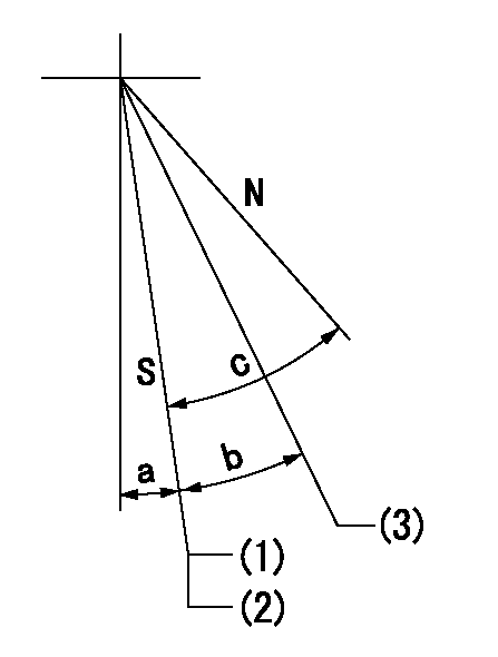
N:Pump normal
S:Stop the pump.
(1)Rack position aa or less, pump speed bb
(2)Set the stopper bolt so that speed = cc, rack position = dd and confirm non-injection (with the speed lever at Full).
(3)Rack position = approximately ee.
----------
aa=8mm bb=325r/min cc=1700r/min dd=6.5-0.5mm ee=16mm
----------
a=8deg+-5deg b=15deg+-3deg c=25deg+-5deg
----------
aa=8mm bb=325r/min cc=1700r/min dd=6.5-0.5mm ee=16mm
----------
a=8deg+-5deg b=15deg+-3deg c=25deg+-5deg
0000001501 MICRO SWITCH
Adjustment of the micro-switch
Adjust the bolt to obtain the following lever position when the micro-switch is ON.
(1)Speed N1
(2)Rack position Ra
----------
N1=350r/min Ra=9.5mm
----------
----------
N1=350r/min Ra=9.5mm
----------
Timing setting
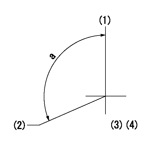
(1)Pump vertical direction
(2)Position of gear mark '3' at No 1 cylinder's beginning of injection
(3)B.T.D.C.: aa
(4)-
----------
aa=10deg
----------
a=(120deg)
----------
aa=10deg
----------
a=(120deg)
Information:
1. Thoroughly clean the area around each fuel injection line connection before removal of any fuel injection lines. 2. Remove bolts (3) and (5) that fasten the mounting brackets to the cylinder head.3. Disconnect all fuel injection line nuts (2) at the fuel injection pump housing.
Do not let the tops of fuel injection nozzles (4) turn when fuel injection line nuts (6) are tightened. The nozzles will be damaged if the top of the nozzle turns in the body. The engine will be damaged if a defective fuel injection nozzle is used because the shape of fuel (spray pattern) that comes out of the nozzles will not be correct.
4. Use two wrenches, one to hold fuel injection nozzles (4) so they will not turn and one to disconnect fuel injection lines (1) from the nozzles.5. Remove fuel injection lines (1) from the engine. Put caps and plugs on the nozzles, fuel injection lines and fuel injection pump housing to keep dirt from entering the fuel system. The following steps are for installation of the fuel injection lines.6. Make sure the fuel injection lines are clean and dry.7. Put fuel injection lines (1) in position. Install all fuel injection line nuts (2) and (6) until they are finger tighten.8. Use a torque wrench and Tool (A) to tighten all fuel injection line nuts (2) to a torque of 41 7 N m (30 5 lb ft).
Do not let the tops of fuel injection nozzles (4) turn when the fuel injection lines are tightened. The nozzles will be damaged if the top of the nozzle turns in the body. The engine will be damaged if a defective fuel injection nozzle is used because the shape of fuel (spray pattern) that comes out of the nozzles will not be correct.
9. Use a wrench to hold fuel injection nozzles (4) so they will not turn. Use a torque wrench and Tool (A) to tighten all fuel injection line nuts (6) to a torque of 41 7 N m (30 5 lb ft).10. Install bolts (3) and (5) that fasten the mounting brackets to the cylinder head.11. Remove (bleed) the air from the fuel system. See the Operation & Maintenance Manual.