Information injection-pump assembly
ZEXEL
101491-0750
1014910750
ISUZU
8970850670
8970850670
Rating:
Service parts 101491-0750 INJECTION-PUMP ASSEMBLY:
1.
_
6.
COUPLING PLATE
7.
COUPLING PLATE
8.
_
9.
_
11.
Nozzle and Holder
8-97119-858-0
12.
Open Pre:MPa(Kqf/cm2)
18.1{185}
15.
NOZZLE SET
Cross reference number
ZEXEL
101491-0750
1014910750
ISUZU
8970850670
8970850670
Zexel num
Bosch num
Firm num
Name
Calibration Data:
Adjustment conditions
Test oil
1404 Test oil ISO4113 or {SAEJ967d}
1404 Test oil ISO4113 or {SAEJ967d}
Test oil temperature
degC
40
40
45
Nozzle and nozzle holder
105780-8140
Bosch type code
EF8511/9A
Nozzle
105780-0000
Bosch type code
DN12SD12T
Nozzle holder
105780-2080
Bosch type code
EF8511/9
Opening pressure
MPa
17.2
Opening pressure
kgf/cm2
175
Injection pipe
Outer diameter - inner diameter - length (mm) mm 6-2-600
Outer diameter - inner diameter - length (mm) mm 6-2-600
Overflow valve
131424-4920
Overflow valve opening pressure
kPa
127
107
147
Overflow valve opening pressure
kgf/cm2
1.3
1.1
1.5
Tester oil delivery pressure
kPa
157
157
157
Tester oil delivery pressure
kgf/cm2
1.6
1.6
1.6
Direction of rotation (viewed from drive side)
Right R
Right R
Injection timing adjustment
Direction of rotation (viewed from drive side)
Right R
Right R
Injection order
1-3-4-2
Pre-stroke
mm
3.2
3.15
3.25
Rack position
Point A R=A
Point A R=A
Beginning of injection position
Drive side NO.1
Drive side NO.1
Difference between angles 1
Cal 1-3 deg. 90 89.5 90.5
Cal 1-3 deg. 90 89.5 90.5
Difference between angles 2
Cal 1-4 deg. 180 179.5 180.5
Cal 1-4 deg. 180 179.5 180.5
Difference between angles 3
Cyl.1-2 deg. 270 269.5 270.5
Cyl.1-2 deg. 270 269.5 270.5
Injection quantity adjustment
Adjusting point
-
Rack position
10.6
Pump speed
r/min
1050
1050
1050
Average injection quantity
mm3/st.
56.4
54.8
58
Max. variation between cylinders
%
0
-3.5
3.5
Basic
*
Fixing the rack
*
Standard for adjustment of the maximum variation between cylinders
*
Injection quantity adjustment_02
Adjusting point
H
Rack position
9.9+-0.5
Pump speed
r/min
300
300
300
Average injection quantity
mm3/st.
12.5
11.2
13.8
Max. variation between cylinders
%
0
-10
10
Fixing the rack
*
Standard for adjustment of the maximum variation between cylinders
*
Injection quantity adjustment_03
Adjusting point
A
Rack position
R1(10.6)
Pump speed
r/min
1050
1050
1050
Average injection quantity
mm3/st.
56.4
55.4
57.4
Basic
*
Fixing the lever
*
Injection quantity adjustment_04
Adjusting point
B
Rack position
R1+0.15
Pump speed
r/min
1750
1750
1750
Average injection quantity
mm3/st.
67.7
64.5
70.9
Fixing the lever
*
Injection quantity adjustment_05
Adjusting point
I
Rack position
-
Pump speed
r/min
100
100
100
Average injection quantity
mm3/st.
78.5
62.5
94.5
Fixing the lever
*
Timer adjustment
Pump speed
r/min
1425--
Advance angle
deg.
0
0
0
Remarks
Start
Start
Timer adjustment_02
Pump speed
r/min
1375
Advance angle
deg.
0.5
Timer adjustment_03
Pump speed
r/min
1750
Advance angle
deg.
5
4.5
5.5
Remarks
Finish
Finish
Test data Ex:
Governor adjustment
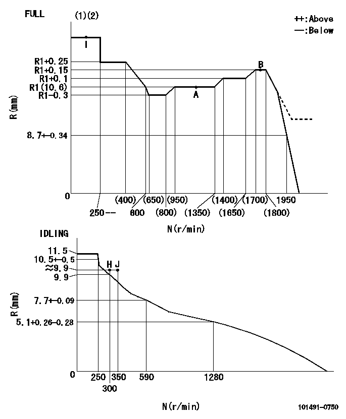
N:Pump speed
R:Rack position (mm)
(1)Torque cam stamping: T1
(2)Tolerance for racks not indicated: +-0.05mm.
----------
T1=G35
----------
----------
T1=G35
----------
Speed control lever angle
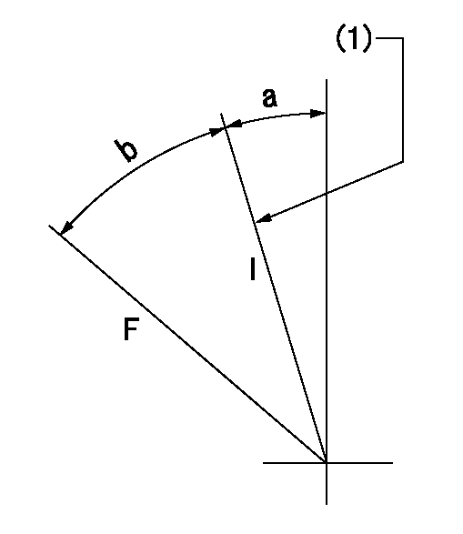
F:Full speed
I:Idle
(1)Stopper bolt set position 'H'
----------
----------
a=5.5deg+-5deg b=34.5deg+-3deg
----------
----------
a=5.5deg+-5deg b=34.5deg+-3deg
Stop lever angle
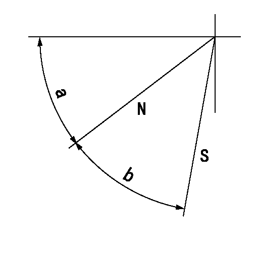
N:Pump normal
S:Stop the pump.
----------
----------
a=45deg+-5deg b=29deg+-5deg
----------
----------
a=45deg+-5deg b=29deg+-5deg
Timing setting
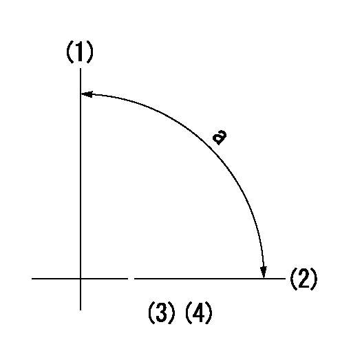
(1)Pump vertical direction
(2)Position of gear mark 'CC' at No 1 cylinder's beginning of injection
(3)B.T.D.C.: aa
(4)-
----------
aa=17deg
----------
a=(90deg)
----------
aa=17deg
----------
a=(90deg)
Information:
Dealer S.O.S. Lab Information:
The SOS Infrared Analysis limit for Allowable Soot is 100% and should be used for all oils. If Caterpillar-brand DEO CF-4 oil is used, then a maximum limit of 130% soot can be used for the 950F. This 130% allowable soot limit does NOT apply to other brands of CF-4 oil because the level of soot dispersent additives in other brands of oil is unknown and varies considerably. Of course, other oil conditions such as wear metal content, "dirt", oxidation, fuel dilution, etc. should also be monitored.
Customer Information
Advise Customers and maintenance personnel of the following information:
These engine updates are intended to reduce 950F engine oil sooting/sludging during the recommended 250 hour engine oil/filter change interval.
1. After this Update, the oil refill is 31 Liters (8.25 U.S. Gallons, or 7.0 Imperial Gallons) due to the new larger engine oil pan and new oil level gauge (dipstick) which raises the liquid level slightly. The former engine oil refill capacity was 20 Liters (5.2 U.S. Gallons, 4.4 Imperial Gallons). Failure to install the new larger quantity of oil may result in oil starvation and engine damage. Customers should inform their maintenance personnel of the new larger Engine Crankcase capacity.2. The recommended engine oil/filter change interval is 250 hours, and should NOT be exceeded, even with the new larger oil capacity. The recommended oil is API Specification CF-4, which has more dispersant additives than either CE or CD oils. If Caterpillar-brand oil is used, be sure to use DEO CF-4 instead of DEO CD.3. If an oil other than API Specification CF-4 is used, such as CD, or CCMC-D4 in Europe, then the engine oil/filter change interval should be shortened. Monitor oil condition with Scheduled Oil Sampling (S-O-S), including Infrared analysis to determine soot level, and establish an acceptable oil/filter change interval.4. Applications at altitudes over 1525 M (5000 feet) may need to use somewhat shorter engine oil/filter intervals. Caterpillar recommends the use of S-O-S, including infrared analysis, to monitor engine oil condition, including soot. The recommendations concerning shorter engine oil and filter change intervals when using of high-sulphur fuel have not changed.5. For machines which have been experiencing excessive sooting or sludging of the engine oil, Caterpillar recommends that customers temporarily shorten the engine oil and filter change interval to approximately 100 hours for the next 300 hours of operation to allow the fresh engine oil to loosen & dissolve any existing soot deposits that may still be inside the engine. Then, return to the recommended oil and filter change interval of 250 hours (also see items 3 and 4 above).
Illustration 1
Illustration 2
VALVE COVER TIGHTENING SEQUENCE Illustration 3
Illustration 4
Illustration 5For Machines With S/N Prefixes Of 4DJ, 7ZF, Or 5SK
Illustration 6For Machines With S/N Prefixes Of 6YG, 5PJ, Or 6LJ
Illustration 7
