Information injection-pump assembly
ZEXEL
101491-0672
1014910672
ISUZU
8970480482
8970480482
Rating:
Cross reference number
ZEXEL
101491-0672
1014910672
ISUZU
8970480482
8970480482
Zexel num
Bosch num
Firm num
Name
101491-0672
8970480482 ISUZU
INJECTION-PUMP ASSEMBLY
4BE1 * K
4BE1 * K
Calibration Data:
Adjustment conditions
Test oil
1404 Test oil ISO4113 or {SAEJ967d}
1404 Test oil ISO4113 or {SAEJ967d}
Test oil temperature
degC
40
40
45
Nozzle and nozzle holder
105780-8140
Bosch type code
EF8511/9A
Nozzle
105780-0000
Bosch type code
DN12SD12T
Nozzle holder
105780-2080
Bosch type code
EF8511/9
Opening pressure
MPa
17.2
Opening pressure
kgf/cm2
175
Injection pipe
Outer diameter - inner diameter - length (mm) mm 6-2-600
Outer diameter - inner diameter - length (mm) mm 6-2-600
Overflow valve
131424-4920
Overflow valve opening pressure
kPa
127
107
147
Overflow valve opening pressure
kgf/cm2
1.3
1.1
1.5
Tester oil delivery pressure
kPa
157
157
157
Tester oil delivery pressure
kgf/cm2
1.6
1.6
1.6
Direction of rotation (viewed from drive side)
Right R
Right R
Injection timing adjustment
Direction of rotation (viewed from drive side)
Right R
Right R
Injection order
1-3-4-2
Pre-stroke
mm
3.2
3.15
3.25
Rack position
Point A R=A
Point A R=A
Beginning of injection position
Drive side NO.1
Drive side NO.1
Difference between angles 1
Cal 1-3 deg. 90 89.5 90.5
Cal 1-3 deg. 90 89.5 90.5
Difference between angles 2
Cal 1-4 deg. 180 179.5 180.5
Cal 1-4 deg. 180 179.5 180.5
Difference between angles 3
Cyl.1-2 deg. 270 269.5 270.5
Cyl.1-2 deg. 270 269.5 270.5
Injection quantity adjustment
Adjusting point
-
Rack position
10.6
Pump speed
r/min
1050
1050
1050
Average injection quantity
mm3/st.
56.4
54.8
58
Max. variation between cylinders
%
0
-4
4
Basic
*
Fixing the rack
*
Standard for adjustment of the maximum variation between cylinders
*
Injection quantity adjustment_02
Adjusting point
H
Rack position
9.9+-0.5
Pump speed
r/min
300
300
300
Average injection quantity
mm3/st.
12.5
11.2
13.8
Max. variation between cylinders
%
0
-10
10
Fixing the rack
*
Standard for adjustment of the maximum variation between cylinders
*
Injection quantity adjustment_03
Adjusting point
A
Rack position
R1(10.6)
Pump speed
r/min
1050
1050
1050
Average injection quantity
mm3/st.
56.4
55.4
57.4
Basic
*
Fixing the lever
*
Injection quantity adjustment_04
Adjusting point
B
Rack position
R1+0.15
Pump speed
r/min
1750
1750
1750
Average injection quantity
mm3/st.
67.7
64.5
70.9
Fixing the lever
*
Injection quantity adjustment_05
Adjusting point
I
Rack position
-
Pump speed
r/min
100
100
100
Average injection quantity
mm3/st.
78.5
62.5
94.5
Fixing the lever
*
Timer adjustment
Pump speed
r/min
1425--
Advance angle
deg.
0
0
0
Remarks
Start
Start
Timer adjustment_02
Pump speed
r/min
1375
Advance angle
deg.
0.5
Timer adjustment_03
Pump speed
r/min
1750
Advance angle
deg.
5
4.5
5.5
Remarks
Finish
Finish
Test data Ex:
Governor adjustment
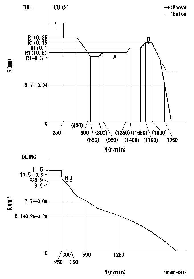
N:Pump speed
R:Rack position (mm)
(1)Torque cam stamping: T1
(2)Tolerance for racks not indicated: +-0.05mm.
----------
T1=G35
----------
----------
T1=G35
----------
Speed control lever angle

F:Full speed
I:Idle
(1)Stopper bolt set position 'H'
----------
----------
a=5.5deg+-5deg b=34.5deg+-3deg
----------
----------
a=5.5deg+-5deg b=34.5deg+-3deg
Stop lever angle
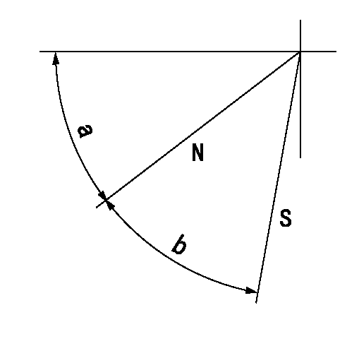
N:Pump normal
S:Stop the pump.
----------
----------
a=45deg+-5deg b=29deg+-5deg
----------
----------
a=45deg+-5deg b=29deg+-5deg
0000001501 ACS

(A) Set screw
(B) Push rod 1
(C) Push rod 2
(D) Cover
1. Aneroid compensator unit adjustment
(1)Select the push rod 2 to obtain L2.
(2)Screw in (A) to obtain L1.
2. Adjustment when mounting the governor.
(1)Set the speed of the pump to N1 r/min and fix the control lever at the full set position.
(2)Screw in the aneroid compensator to obtain the performance shown in the graph above.
(3)As there is hysterisis, measure when the absolute pressure drops.
(4)Hysterisis must not exceed rack position = h1.
----------
N1=1050r/min L1=(1.5)mm L2=11+-0.5mm h1=0.15mm
----------
Ra=R1(10.6)mm Rb=R1-0.45mm Pa=95.4+-5.3kPa(716+-40mmHg) Pb=70.1+-0.7kPa(526+-5mmHg) Q1=56.4+-1cm3/1000st Q2=(43)+-1.6cm3/1000st
----------
N1=1050r/min L1=(1.5)mm L2=11+-0.5mm h1=0.15mm
----------
Ra=R1(10.6)mm Rb=R1-0.45mm Pa=95.4+-5.3kPa(716+-40mmHg) Pb=70.1+-0.7kPa(526+-5mmHg) Q1=56.4+-1cm3/1000st Q2=(43)+-1.6cm3/1000st
Timing setting

(1)Pump vertical direction
(2)Position of gear mark 'CC' at No 1 cylinder's beginning of injection
(3)B.T.D.C.: aa
(4)-
----------
aa=17deg
----------
a=(90deg)
----------
aa=17deg
----------
a=(90deg)
Information:
(1) Endplay for shaft (new) ... 0.102 0.025 mm (.004 .001 in) Maximum permissible endplay (worn) ... 0.20 mm (.008 in)(2) Thickness of thrust bearing (where thrust rings contact bearing) ... 5.36 0.03 mm (.211 .001 in)(3) Diameter of shaft (new) ... 12.697 to 12.705 mm (.4999 to .5002 in) Bore in the bearing (new) ... 12.741 to 12.748 mm (.5016 to .5019 in)Maximum permissible clearance between bearing and shaft (worn) ... 0.05 mm (.002 in)(4) Maximum permissible gap of oil seal ring, measured in bore of housing ... 0.25 mm (.010 in)
The impeller shaft nut is a left hand thread (CCW).
(5) Install the compressor wheel (at room temperature) as follows: a. Put compressor wheel on the shaft.b. Put a small amount of clean engine oil on the threads.c. Tighten the nut (CCW) to 14 to 17 N m (125 to 150 lb in).d. Loosen the nut and tighten again to 9 N m (80 lb in) plus an additional 60 degrees (1/6 turn).
Do not bend or add stress to the shaft when the nut is loosened or tightened.
(6) Thickness of each thrust ring ... 2.553 0.013 mm (.1005 .0005 in)(7) Bore in housing (new) ... 20.744 to 20.757 mm (.8167 to .8172 in) Outside diameter of the bearing (new) ... 20.630 to 20.643 mm (.8122 to .8127 in)Maximum permissible clearance between bearing and bore in housing (worn) ... 0.15 mm (.006 in)Torque for four nuts (put 5P3931 Anti-Seize Compound on threads) and bolts that hold turbocharger to exhaust manifold ... 55 5 N m (40 4 lb ft)Install the band clamps to hold the cartridge to the compressor housing as follows: a. Tighten clamps to 14 1.1 N m (125 10 lb in)b. Tap (hit) clamp lightly all around.c. Tighten again to ... 14 1.1 N m (125 10 lb in) Put clean engine oil in the oil inlet of the turbocharger after assembly or before installation to provide start up lubrication and/or storage protection.
Have questions with 101491-0672?
Group cross 101491-0672 ZEXEL
Isuzu
101491-0672
8970480482
INJECTION-PUMP ASSEMBLY
4BE1
4BE1