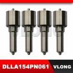
Information injection-pump assembly
ZEXEL
101491-0556
1014910556
ISUZU
8970439730
8970439730
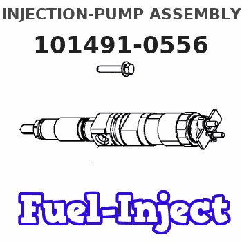
Rating:
Service parts 101491-0556 INJECTION-PUMP ASSEMBLY:
1.
_
6.
COUPLING PLATE
7.
COUPLING PLATE
8.
_
9.
_
11.
Nozzle and Holder
8-97021-703-1
12.
Open Pre:MPa(Kqf/cm2)
21.6{220}
15.
NOZZLE SET
Cross reference number
ZEXEL
101491-0556
1014910556
ISUZU
8970439730
8970439730
Zexel num
Bosch num
Firm num
Name
Calibration Data:
Adjustment conditions
Test oil
1404 Test oil ISO4113 or {SAEJ967d}
1404 Test oil ISO4113 or {SAEJ967d}
Test oil temperature
degC
40
40
45
Nozzle and nozzle holder
105780-8140
Bosch type code
EF8511/9A
Nozzle
105780-0000
Bosch type code
DN12SD12T
Nozzle holder
105780-2080
Bosch type code
EF8511/9
Opening pressure
MPa
17.2
Opening pressure
kgf/cm2
175
Injection pipe
Outer diameter - inner diameter - length (mm) mm 6-2-600
Outer diameter - inner diameter - length (mm) mm 6-2-600
Overflow valve
131424-4920
Overflow valve opening pressure
kPa
127
107
147
Overflow valve opening pressure
kgf/cm2
1.3
1.1
1.5
Tester oil delivery pressure
kPa
157
157
157
Tester oil delivery pressure
kgf/cm2
1.6
1.6
1.6
Direction of rotation (viewed from drive side)
Right R
Right R
Injection timing adjustment
Direction of rotation (viewed from drive side)
Right R
Right R
Injection order
1-3-4-2
Pre-stroke
mm
3.8
3.75
3.85
Rack position
After adjusting injection quantity. R=A
After adjusting injection quantity. R=A
Beginning of injection position
Drive side NO.1
Drive side NO.1
Difference between angles 1
Cal 1-3 deg. 90 89.5 90.5
Cal 1-3 deg. 90 89.5 90.5
Difference between angles 2
Cal 1-4 deg. 180 179.5 180.5
Cal 1-4 deg. 180 179.5 180.5
Difference between angles 3
Cyl.1-2 deg. 270 269.5 270.5
Cyl.1-2 deg. 270 269.5 270.5
Injection quantity adjustment
Adjusting point
-
Rack position
12.4
Pump speed
r/min
1050
1050
1050
Average injection quantity
mm3/st.
58.8
57.2
60.4
Max. variation between cylinders
%
0
-2.5
2.5
Basic
*
Fixing the rack
*
Standard for adjustment of the maximum variation between cylinders
*
Injection quantity adjustment_02
Adjusting point
H
Rack position
9.5+-0.5
Pump speed
r/min
325
325
325
Average injection quantity
mm3/st.
13.3
12
14.6
Max. variation between cylinders
%
0
-14
14
Fixing the rack
*
Standard for adjustment of the maximum variation between cylinders
*
Injection quantity adjustment_03
Adjusting point
A
Rack position
R1(12.4)
Pump speed
r/min
1050
1050
1050
Average injection quantity
mm3/st.
58.8
57.8
59.8
Basic
*
Fixing the lever
*
Injection quantity adjustment_04
Adjusting point
B
Rack position
R1+0.5
Pump speed
r/min
1750
1750
1750
Average injection quantity
mm3/st.
77.1
73.1
81.1
Fixing the lever
*
Injection quantity adjustment_05
Adjusting point
I
Rack position
-
Pump speed
r/min
100
100
100
Average injection quantity
mm3/st.
92
92
124
Fixing the lever
*
Timer adjustment
Pump speed
r/min
1530--
Advance angle
deg.
0
0
0
Remarks
Start
Start
Timer adjustment_02
Pump speed
r/min
1480
Advance angle
deg.
0.3
Timer adjustment_03
Pump speed
r/min
1775
Advance angle
deg.
4.5
4
5
Remarks
Finish
Finish
Test data Ex:
Governor adjustment
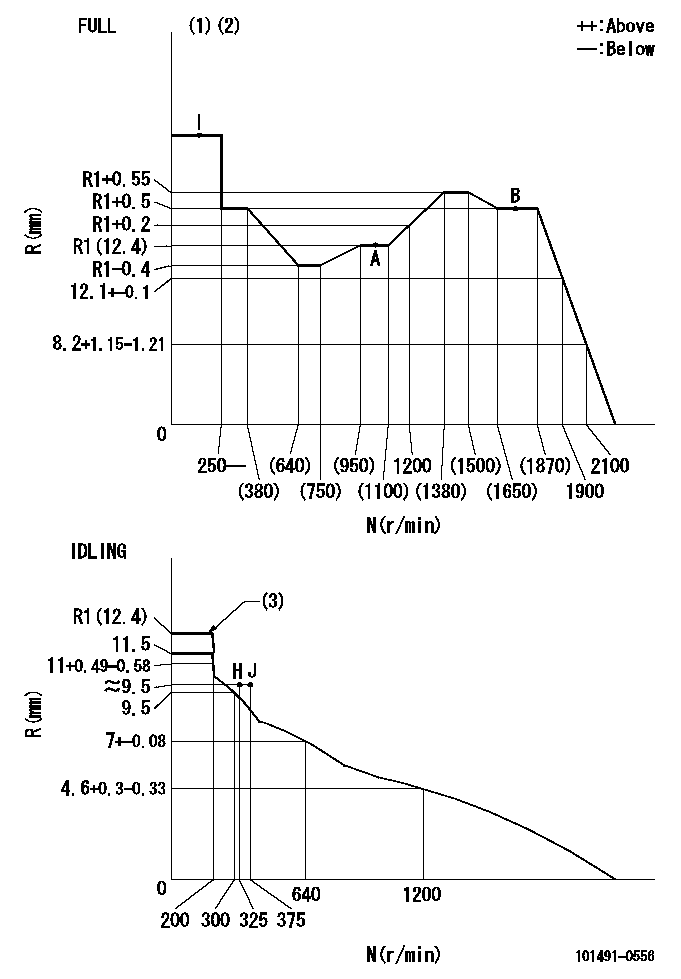
N:Pump speed
R:Rack position (mm)
(1)Torque cam stamping: T1
(2)Tolerance for racks not indicated: +-0.05mm.
(3)At delivery (at R = A, N = N1)
----------
T1=G20 N1=100r/min
----------
----------
T1=G20 N1=100r/min
----------
Speed control lever angle
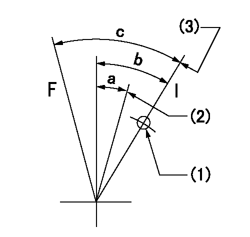
F:Full speed
I:Idle
(1)Use the hole at R = aa
(2)Set the idle side stopper bolt so that speed = bb and rack position = cc (at delivery).
(3)Stopper bolt set position 'H'
----------
aa=50mm bb=100r/min cc=R1(12.4)mm
----------
a=(23.5deg) b=27.5deg+-5deg c=(38deg)+-3deg
----------
aa=50mm bb=100r/min cc=R1(12.4)mm
----------
a=(23.5deg) b=27.5deg+-5deg c=(38deg)+-3deg
Stop lever angle
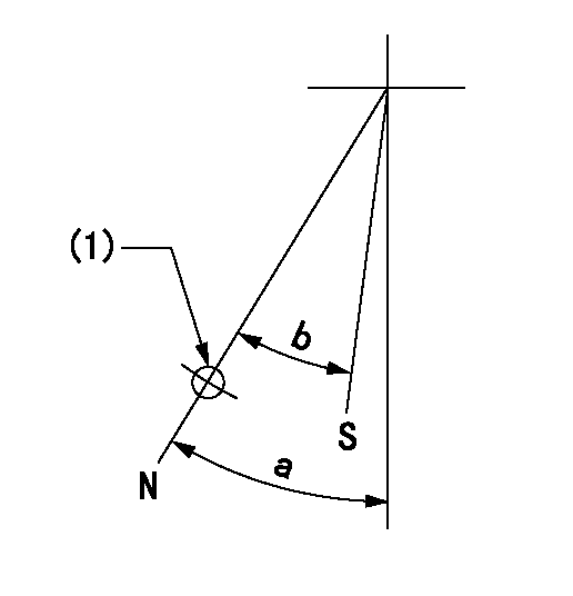
N:Pump normal
S:Stop the pump.
(1)Use the hole at R = aa
----------
aa=64mm
----------
a=45deg+-5deg b=29deg+-5deg
----------
aa=64mm
----------
a=45deg+-5deg b=29deg+-5deg
0000001501 I/P WITH LOAD PLUNGER ADJ
Plunger assembly number: PL (stamping: ST)
1. Adjustment procedures
(1)Insert the pre-stroke adjusting shims L1 for each cylinder.
(2)Adjust injection quantity.(max. var. bet. cyl. idling a1, full a2)
(3)At basic point A, adjust so that the pre-stroke is L2.
(4)Reconfirm the injection quantity.
----------
PL=131154-1820 ST=A260 L1=1mm L2=3.8+-0.05mm a1=+-14% a2=+-2.5%
----------
----------
PL=131154-1820 ST=A260 L1=1mm L2=3.8+-0.05mm a1=+-14% a2=+-2.5%
----------
Timing setting

(1)Pump vertical direction
(2)Position of gear mark 'CC' at No 1 cylinder's beginning of injection
(3)B.T.D.C.: aa
(4)-
----------
aa=15deg
----------
a=(100deg)
----------
aa=15deg
----------
a=(100deg)
Information:
(1) Inside diameter of rod for small end bushing ... 38.8938 to 38.9192 mm (1.53125 to 1.53225 in)(2) Outside diameter of bushing for piston pin ... 38.989 to 39.027 mm (1.5350 to 1.5365 in) Inside diameter of bushing for piston pin (after reaming) ... 34.9441 to 34.9631 mm (1.37575 to 1.37650 in)Clearance between small end bushing and piston pin ... 0.0191 to 0.0432 mm (.00075 to .00170 in)(3) Distance between center of piston pin and center of crankshaft bearing ... 219.05 to 219.10 mm (8.624 to 8.626 in)(4) Outside diameter of connecting rod bearing ... 67.221 mm (2.6465 in) Inside diameter of connecting rod bearing (standard) ... 63.520 to 63.548 mm (2.5008 to 2.5019 in)Bearings available for reground (machined) journals of crankshaft with undersize ... 0.25, 0.51 and 0.76 mm (.010, .020 and .030 in)Shell thickness ... 1.836 to 1.844 mm (.0723 to .0726 in)(5) Inside diameter of rod for big end bearing ... 67.208 to 67.221 mm (2.6460 to 2.6465 in)(6) Torque for connecting rod nuts: Cadmium plated nuts (silver color) ... 100 N m (75 lb ft)Phosphated nuts (dull black color) ... 130 N m (95 lb ft)C4.236 Engines
(1) Inside diameter of rod for small end bushing ... 42.0688 to 42.0942 mm (1.65625 to 1.65725 in)(2) Outside diameter of bushing for piston pin ... 42.1577 to 42.1958 mm (1.65975 to 1.66125 in) Inside diameter of bushing for piston pin (after reaming) ... 38.1191 to 38.1381 mm (1.50075 to 1.50150 in)Clearance between small end bushing and piston pin ... 0.0191 to 0.0432 mm (.00075 to .00170 in)(3) Distance between center of piston pin and center of crankshaft bearing ... 219.05 to 219.10 mm (8.624 to 8.626 in)(4) Outside diameter of connecting rod bearing ... 67.221 mm (2.6465 in) Inside diameter of connecting rod bearing (standard) ... 63.520 to 63.548 mm (2.5008 to 2.5019 in)Bearing available for reground (machined) journals of crankshaft with undersize ... 0.25, 0.51 and 0.76 mm (.010, .020 and .030 in)Shell thickness ... 1.836 to 1.844 mm (.0723 to .0726 in)(5) Inside diameter of rod for big end bearing ... 67.208 to 67.221 mm (2.6460 to 2.6465 in)(6) Torque for connecting rod nuts: Cadmium plated nuts (silver color) ... 100 N m (75 lb ft)Phosphated nuts (dull black color) ... 130 N m (95 lb ft)
(1) Inside diameter of rod for small end bushing ... 42.0688 to 42.0942 mm (1.65625 to 1.65725 in)(2) Outside diameter of bushing for piston pin ... 42.1577 to 42.1958 mm (1.65975 to 1.66125 in) Inside diameter of bushing for piston pin (after reaming) ... 38.1191 to 38.1381 mm (1.50075 to 1.50150 in)Clearance between small end bushing and piston pin ... 0.0191 to 0.0432 mm (.00075 to .00170 in)(3) Distance between center of piston pin and center of crankshaft bearing ... 219.05 to 219.10 mm (8.624 to 8.626 in)(4) Outside diameter of connecting rod bearing ... 67.221 mm (2.6465 in) Inside diameter of connecting rod bearing (standard) ... 63.520 to 63.548 mm (2.5008 to 2.5019 in)Bearing available for reground (machined) journals of crankshaft with undersize ... 0.25, 0.51 and 0.76 mm (.010, .020 and .030 in)Shell thickness ... 1.836 to 1.844 mm (.0723 to .0726 in)(5) Inside diameter of rod for big end bearing ... 67.208 to 67.221 mm (2.6460 to 2.6465 in)(6) Torque for connecting rod nuts: Cadmium plated nuts (silver color) ... 100 N m (75 lb ft)Phosphated nuts (dull black color) ... 130 N m (95 lb ft)
