Information injection-pump assembly
ZEXEL
101491-0490
1014910490
ISUZU
8970110150
8970110150
Rating:
Cross reference number
ZEXEL
101491-0490
1014910490
ISUZU
8970110150
8970110150
Zexel num
Bosch num
Firm num
Name
Calibration Data:
Adjustment conditions
Test oil
1404 Test oil ISO4113 or {SAEJ967d}
1404 Test oil ISO4113 or {SAEJ967d}
Test oil temperature
degC
40
40
45
Nozzle and nozzle holder
105780-8140
Bosch type code
EF8511/9A
Nozzle
105780-0000
Bosch type code
DN12SD12T
Nozzle holder
105780-2080
Bosch type code
EF8511/9
Opening pressure
MPa
17.2
Opening pressure
kgf/cm2
175
Injection pipe
Outer diameter - inner diameter - length (mm) mm 6-2-600
Outer diameter - inner diameter - length (mm) mm 6-2-600
Overflow valve
131424-4920
Overflow valve opening pressure
kPa
127
107
147
Overflow valve opening pressure
kgf/cm2
1.3
1.1
1.5
Tester oil delivery pressure
kPa
157
157
157
Tester oil delivery pressure
kgf/cm2
1.6
1.6
1.6
Direction of rotation (viewed from drive side)
Right R
Right R
Injection timing adjustment
Direction of rotation (viewed from drive side)
Right R
Right R
Injection order
1-3-4-2
Pre-stroke
mm
3.8
3.75
3.85
Rack position
After adjusting injection quantity. R=A
After adjusting injection quantity. R=A
Beginning of injection position
Drive side NO.1
Drive side NO.1
Difference between angles 1
Cal 1-3 deg. 90 89.5 90.5
Cal 1-3 deg. 90 89.5 90.5
Difference between angles 2
Cal 1-4 deg. 180 179.5 180.5
Cal 1-4 deg. 180 179.5 180.5
Difference between angles 3
Cyl.1-2 deg. 270 269.5 270.5
Cyl.1-2 deg. 270 269.5 270.5
Injection quantity adjustment
Adjusting point
-
Rack position
13.2
Pump speed
r/min
1050
1050
1050
Average injection quantity
mm3/st.
74.1
72.5
75.7
Max. variation between cylinders
%
0
-2.5
2.5
Basic
*
Fixing the rack
*
Standard for adjustment of the maximum variation between cylinders
*
Injection quantity adjustment_02
Adjusting point
H
Rack position
9.5+-0.5
Pump speed
r/min
300
300
300
Average injection quantity
mm3/st.
10.2
8.9
11.5
Max. variation between cylinders
%
0
-14
14
Fixing the rack
*
Standard for adjustment of the maximum variation between cylinders
*
Injection quantity adjustment_03
Adjusting point
A
Rack position
R1(13.2)
Pump speed
r/min
1050
1050
1050
Average injection quantity
mm3/st.
74.1
73.1
75.1
Basic
*
Fixing the lever
*
Injection quantity adjustment_04
Adjusting point
B
Rack position
R1+0.45
Pump speed
r/min
1750
1750
1750
Average injection quantity
mm3/st.
88.4
84.4
92.4
Fixing the lever
*
Injection quantity adjustment_05
Adjusting point
I
Rack position
-
Pump speed
r/min
100
100
100
Average injection quantity
mm3/st.
92
92
124
Fixing the lever
*
Timer adjustment
Pump speed
r/min
1550--
Advance angle
deg.
0
0
0
Remarks
Start
Start
Timer adjustment_02
Pump speed
r/min
1500
Advance angle
deg.
0.3
Timer adjustment_03
Pump speed
r/min
1800
Advance angle
deg.
4.5
4
5
Remarks
Finish
Finish
Test data Ex:
Governor adjustment
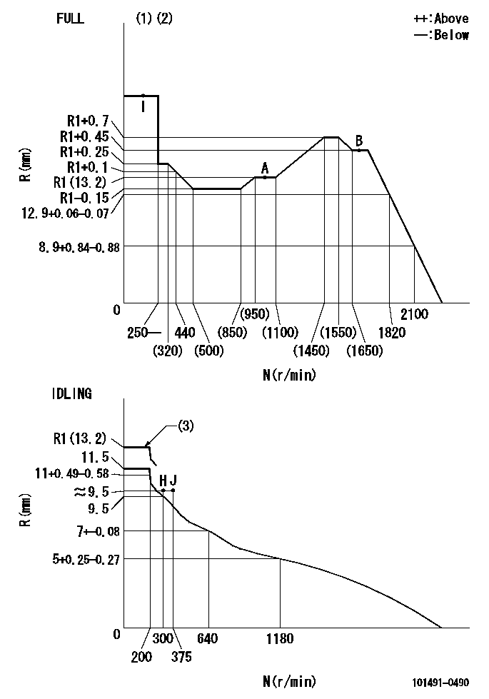
N:Pump speed
R:Rack position (mm)
(1)Torque cam stamping: T1
(2)Tolerance for racks not indicated: +-0.05mm.
(3)At delivery (at R = A, N = N1)
----------
T1=E68 N1=100r/min
----------
----------
T1=E68 N1=100r/min
----------
Speed control lever angle
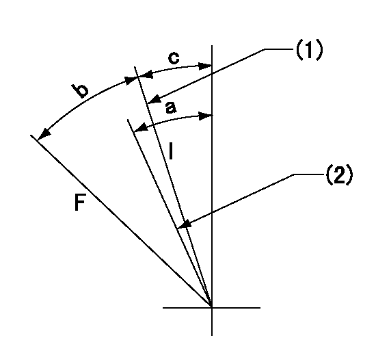
F:Full speed
I:Idle
(1)Stopper bolt set position 'H'
(2)Set the idle side stopper bolt at speed = aa and rack position = bb (at delivery)
----------
aa=100r/min bb=R1(13.2)mm
----------
a=(8deg) b=35deg+-3deg c=2.5deg+-5deg
----------
aa=100r/min bb=R1(13.2)mm
----------
a=(8deg) b=35deg+-3deg c=2.5deg+-5deg
Stop lever angle
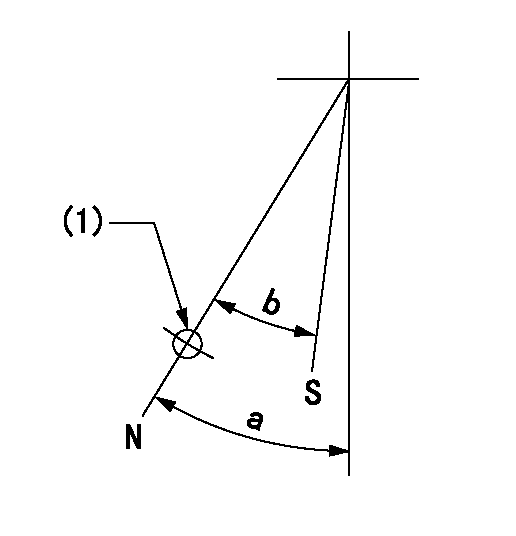
N:Pump normal
S:Stop the pump.
(1)Use the hole at R = aa
----------
aa=64mm
----------
a=45deg+-5deg b=29deg+-5deg
----------
aa=64mm
----------
a=45deg+-5deg b=29deg+-5deg
0000001501 I/P WITH LOAD PLUNGER ADJ
Plunger assembly number: PL (stamping: ST)
1. Adjustment procedures
(1)Insert the pre-stroke adjusting shims L1 for each cylinder.
(2)Adjust injection quantity.(max. var. bet. cyl. idling a1, full a2)
(3)At basic point A, adjust so that the pre-stroke is L2.
(4)Reconfirm the injection quantity.
----------
PL=131154-1820 ST=A260 L1=1mm L2=3.8+-0.05mm a1=+-14% a2=+-2.5%
----------
----------
PL=131154-1820 ST=A260 L1=1mm L2=3.8+-0.05mm a1=+-14% a2=+-2.5%
----------
0000001601 FICD
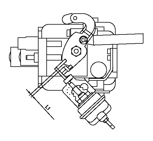
1. FICD adjustment
(1)FICD adjustment not necessary.
(2)Set the clearance between the actuator rod and speed lever to approx. L1.
----------
L1=3+1mm
----------
----------
L1=3+1mm
----------
Timing setting

(1)Pump vertical direction
(2)Position of gear mark 'CC' at No 1 cylinder's beginning of injection
(3)B.T.D.C.: aa
(4)-
----------
aa=15deg
----------
a=(90deg)
----------
aa=15deg
----------
a=(90deg)
Information:
3T6352 Alternator 24V 35A (Delco-Remy Number 1117647)
Load battery with a carbon pile (6V4930 Battery Load Tester) to get maximum alternator output.Polarity ... Negative GroundRotation ... Either DirectionOutput voltage ... 27.5 1.0VSpeed for testing (rpm) ... 5000Output (hot) ... 35APositive output terminal torque ... 6.2 to 8.0 N m (55 to 71 lb in)(1) Ground terminal torque ... 1.7 to 2.9 N m (15 to 26 lb in)(2) Shaft nut torque ... 95 to 110 N m (70 to 80 lb ft) 3T6354 Regulator (Delco-Remy Number 1116405) - Inside Alternator. For use with 3T6352 Alternators
Voltage setting ... No AdjustmentPermissible voltage range ... 26 to 30VBosch
7N9720 Alternator 24V 35A (Bosch Number 0-122-469-001)
Load battery with a carbon pile (6V4930 Battery Load Tester) to get maximum alternator output.Polarity ... Negative GroundRotation ... Either DirectionSpeed for testing (rpm) ... 5000Output voltage ... 27.5 1.0VOutput (hot) ... 35A(1) Torque for pulley nut ... 95 to 110 N m (70 to 80 lb ft)(2) Torque for output terminal B+ ... 17 to 22 N m (13 to 16 lb ft)Torque for ground terminal ... 2.1 to 2.8 N m (19 to 25 lb in) 9G7567 Regulator (Bosch Number 1-197-011-000)-under alternator cover. For use with 7N9720 Alternators.
Voltage setting ... No AdjustmentPermissible voltage range ... 26.7 to 28.3VNippondenso
9G4574 24V 35A (Nippondenso Number 100211-0860)
Load battery with a carbon pile (6V4930 Battery Load Tester) to get maximum alternator output.Polarity ... Negative GroundRotation ... Either DirectionSpeed for testing (rpm) ... 5000Output voltage ... 27.5 1.0VOutput (hot) ... 35A(1) Torque for pulley nut ... 95 to 110 N m (70 to 80 lb ft)(2) Torque for output terminal ... 22 to 37 N m (16 to 27 lb ft)(3) Torque for ground terminal ... 3.4 to 5.4 N m (31 to 49 lb in) 7T2798 Regulator (Nippondenso Number 126000-0380) - Inside Alternator. For use with 9G4574 Alternators.
Voltage setting ... No adjustmentPermissible voltage range ... 26.5 to 28.5V