Information injection-pump assembly
ZEXEL
101491-0480
1014910480
ISUZU
8970110160
8970110160
Rating:
Cross reference number
ZEXEL
101491-0480
1014910480
ISUZU
8970110160
8970110160
Zexel num
Bosch num
Firm num
Name
Calibration Data:
Adjustment conditions
Test oil
1404 Test oil ISO4113 or {SAEJ967d}
1404 Test oil ISO4113 or {SAEJ967d}
Test oil temperature
degC
40
40
45
Nozzle and nozzle holder
105780-8140
Bosch type code
EF8511/9A
Nozzle
105780-0000
Bosch type code
DN12SD12T
Nozzle holder
105780-2080
Bosch type code
EF8511/9
Opening pressure
MPa
17.2
Opening pressure
kgf/cm2
175
Injection pipe
Outer diameter - inner diameter - length (mm) mm 6-2-600
Outer diameter - inner diameter - length (mm) mm 6-2-600
Overflow valve
131424-4920
Overflow valve opening pressure
kPa
127
107
147
Overflow valve opening pressure
kgf/cm2
1.3
1.1
1.5
Tester oil delivery pressure
kPa
157
157
157
Tester oil delivery pressure
kgf/cm2
1.6
1.6
1.6
Direction of rotation (viewed from drive side)
Right R
Right R
Injection timing adjustment
Direction of rotation (viewed from drive side)
Right R
Right R
Injection order
1-3-4-2
Pre-stroke
mm
3.8
3.75
3.85
Rack position
After adjusting injection quantity. R=A
After adjusting injection quantity. R=A
Beginning of injection position
Drive side NO.1
Drive side NO.1
Difference between angles 1
Cal 1-3 deg. 90 89.5 90.5
Cal 1-3 deg. 90 89.5 90.5
Difference between angles 2
Cal 1-4 deg. 180 179.5 180.5
Cal 1-4 deg. 180 179.5 180.5
Difference between angles 3
Cyl.1-2 deg. 270 269.5 270.5
Cyl.1-2 deg. 270 269.5 270.5
Injection quantity adjustment
Adjusting point
-
Rack position
13.2
Pump speed
r/min
1050
1050
1050
Average injection quantity
mm3/st.
74.1
72.5
75.7
Max. variation between cylinders
%
0
-2.5
2.5
Basic
*
Fixing the rack
*
Standard for adjustment of the maximum variation between cylinders
*
Injection quantity adjustment_02
Adjusting point
H
Rack position
9.5+-0.5
Pump speed
r/min
300
300
300
Average injection quantity
mm3/st.
10.2
8.9
11.5
Max. variation between cylinders
%
0
-14
14
Fixing the rack
*
Standard for adjustment of the maximum variation between cylinders
*
Injection quantity adjustment_03
Adjusting point
A
Rack position
R1(13.2)
Pump speed
r/min
1050
1050
1050
Average injection quantity
mm3/st.
74.1
73.1
75.1
Basic
*
Fixing the lever
*
Injection quantity adjustment_04
Adjusting point
B
Rack position
R1+0.45
Pump speed
r/min
1750
1750
1750
Average injection quantity
mm3/st.
88.4
84.4
92.4
Fixing the lever
*
Injection quantity adjustment_05
Adjusting point
I
Rack position
-
Pump speed
r/min
100
100
100
Average injection quantity
mm3/st.
92
60
124
Fixing the lever
*
Timer adjustment
Pump speed
r/min
1550--
Advance angle
deg.
0
0
0
Remarks
Start
Start
Timer adjustment_02
Pump speed
r/min
1500
Advance angle
deg.
0.3
Timer adjustment_03
Pump speed
r/min
1800
Advance angle
deg.
4.5
4
5
Remarks
Finish
Finish
Test data Ex:
Governor adjustment

N:Pump speed
R:Rack position (mm)
(1)Torque cam stamping: T1
(2)Tolerance for racks not indicated: +-0.05mm.
(3)At delivery (at R = A, N = N1)
----------
T1=E68 N1=100r/min
----------
----------
T1=E68 N1=100r/min
----------
Speed control lever angle
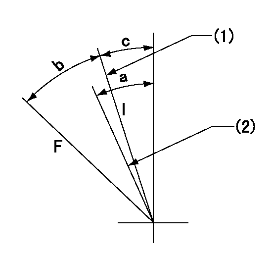
F:Full speed
I:Idle
(1)Stopper bolt set position 'H'
(2)Set the idle side stopper bolt at speed = aa and rack position = bb (at delivery)
----------
aa=100r/min bb=R1(13.2)mm
----------
a=(8deg) b=35deg+-3deg c=2.5deg+-5deg
----------
aa=100r/min bb=R1(13.2)mm
----------
a=(8deg) b=35deg+-3deg c=2.5deg+-5deg
Stop lever angle
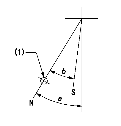
N:Pump normal
S:Stop the pump.
(1)Use the hole at R = aa
----------
aa=64mm
----------
a=45deg+-5deg b=29deg+-5deg
----------
aa=64mm
----------
a=45deg+-5deg b=29deg+-5deg
0000001501 I/P WITH LOAD PLUNGER ADJ
Plunger assembly number: PL (stamping: ST)
1. Adjustment procedures
(1)Insert the pre-stroke adjusting shims L1 for each cylinder.
(2)Adjust injection quantity.(max. var. bet. cyl. idling a1, full a2)
(3)At basic point A, adjust so that the pre-stroke is L2.
(4)Reconfirm the injection quantity.
----------
PL=131154-1820 ST=A260 L1=1mm L2=3.8+-0.05mm a1=+-14% a2=+-2.5%
----------
----------
PL=131154-1820 ST=A260 L1=1mm L2=3.8+-0.05mm a1=+-14% a2=+-2.5%
----------
Timing setting

(1)Pump vertical direction
(2)Position of gear mark 'CC' at No 1 cylinder's beginning of injection
(3)B.T.D.C.: aa
(4)-
----------
aa=15deg
----------
a=(90deg)
----------
aa=15deg
----------
a=(90deg)
Information:
(1) Thickness of spacer plate ... 9.970 0.025 mm (.3925 .0010 in.) Thickness of spacer plate gasket ... 0.208 0.025 mm (.0082 .0010 in.) For height of liner over top of spacer plate make reference to Cylinder Liner Projection.(2) Camshaft bearing bore (installed) ... 58.80 0.06 mm (2.315 .002 in.) Bore in block for camshaft bearings ... 65.100 0.025 mm (2.5630 .0010 in.)(3) Bore in block for main bearings (standard size) ... 96.926 0.013 mm (3.8160 .0005 in.) Bore in block for main bearings 0.51 mm (.020 in.) oversize ... 97.436 0.013 mm (3.8361 .0005 in.)(4) Dimension from center of main bearing bore to top of cylinder block (new) ... 383.515 0.165 mm (15.099 .0064 in.)(5) Dimension from center of main bearing bore to bottom of cylinder block (new) ... 153.99 0.10 mm (6.063 .004 in.)(6) Torque for bolts holding bearing caps for main bearings: a. Put 2P2506 Thread Lubricant on threads and washer face.b. Tighten all bolts to ... 41 4 N m (30 3 lb ft)c. Put a mark on each bolt and cap.d. Tighten all bolts from mark ... 90 5° Install bearing caps with the part number toward the front of the engine. Be sure that the mark (number) on the bearing cap next to the bolt hole is in agreement with the mark in the cylinder block.(7) Clearance between main bearing cap and cylinder block ... 0.033 mm (.0013 in.)tight to ... 0.043 mm (.0017 in.) loose Main bearing cap width ... 165.095 0.020 mm (6.4998 .0008 in.)Width of cylinder block for main bearing cap ... 165.100 0.018 mm (6.5000 .0007 in.) (8) Piston cooling orifice.
There are holes in the bores for the main bearings, between the cylinders for piston cooler orifices. These holes must have orifices (8) installed.
(9) Distance two dowels extend from the surface of the cylinder block ... 19.8 0.5 mm (.78 .02 in.)(10) Distance hollow dowel extends from the surface of the cylinder block ... 16.0 0.5 mm (.63 .02 in.)(11) Depth to install two dowels below the surface of the cylinder block (apply loctite #11358) ... 1.0 0.5 mm (.04 .02 in.)(12) Distance dowels extend from the front face of the cylinder block ... 22.4 0.5 mm (.88 .02 in.)(13) Distance stud extends from the front face of the cylinder block ... 15.7 0.5 mm (.62 .02 in.)(14) Distance two dowels extend from the rear face of the cylinder block ... 12.7 0.5 mm (.50 .02 in.)