Information injection-pump assembly
BOSCH
9 400 614 285
9400614285
ZEXEL
101491-0462
1014910462
ISUZU
8943256043
8943256043
Rating:
Service parts 101491-0462 INJECTION-PUMP ASSEMBLY:
1.
_
6.
COUPLING PLATE
7.
COUPLING PLATE
8.
_
9.
_
10.
NOZZLE AND HOLDER ASSY
11.
Nozzle and Holder
12.
Open Pre:MPa(Kqf/cm2)
13.
NOZZLE-HOLDER
14.
NOZZLE
15.
NOZZLE SET
Cross reference number
BOSCH
9 400 614 285
9400614285
ZEXEL
101491-0462
1014910462
ISUZU
8943256043
8943256043
Zexel num
Bosch num
Firm num
Name
Calibration Data:
Adjustment conditions
Test oil
1404 Test oil ISO4113 or {SAEJ967d}
1404 Test oil ISO4113 or {SAEJ967d}
Test oil temperature
degC
40
40
45
Nozzle and nozzle holder
105780-8140
Bosch type code
EF8511/9A
Nozzle
105780-0000
Bosch type code
DN12SD12T
Nozzle holder
105780-2080
Bosch type code
EF8511/9
Opening pressure
MPa
17.2
Opening pressure
kgf/cm2
175
Injection pipe
Outer diameter - inner diameter - length (mm) mm 6-2-600
Outer diameter - inner diameter - length (mm) mm 6-2-600
Overflow valve
131424-4920
Overflow valve opening pressure
kPa
127
107
147
Overflow valve opening pressure
kgf/cm2
1.3
1.1
1.5
Tester oil delivery pressure
kPa
157
157
157
Tester oil delivery pressure
kgf/cm2
1.6
1.6
1.6
Direction of rotation (viewed from drive side)
Right R
Right R
Injection timing adjustment
Direction of rotation (viewed from drive side)
Right R
Right R
Injection order
1-3-4-2
Pre-stroke
mm
3.2
3.15
3.25
Rack position
Point A R=A
Point A R=A
Beginning of injection position
Drive side NO.1
Drive side NO.1
Difference between angles 1
Cal 1-3 deg. 90 89.5 90.5
Cal 1-3 deg. 90 89.5 90.5
Difference between angles 2
Cal 1-4 deg. 180 179.5 180.5
Cal 1-4 deg. 180 179.5 180.5
Difference between angles 3
Cyl.1-2 deg. 270 269.5 270.5
Cyl.1-2 deg. 270 269.5 270.5
Injection quantity adjustment
Adjusting point
-
Rack position
10.7
Pump speed
r/min
1050
1050
1050
Average injection quantity
mm3/st.
58.1
56.5
59.7
Max. variation between cylinders
%
0
-4
4
Basic
*
Fixing the rack
*
Standard for adjustment of the maximum variation between cylinders
*
Injection quantity adjustment_02
Adjusting point
-
Rack position
9.7+-0.5
Pump speed
r/min
300
300
300
Average injection quantity
mm3/st.
8
6.5
9.5
Max. variation between cylinders
%
0
-10
10
Fixing the rack
*
Standard for adjustment of the maximum variation between cylinders
*
Remarks
Adjust only variation between cylinders; adjust governor according to governor specifications.
Adjust only variation between cylinders; adjust governor according to governor specifications.
Injection quantity adjustment_03
Adjusting point
A
Rack position
R1(10.7)
Pump speed
r/min
1050
1050
1050
Average injection quantity
mm3/st.
58.1
57.1
59.1
Basic
*
Fixing the lever
*
Injection quantity adjustment_04
Adjusting point
B
Rack position
R1+0.15
Pump speed
r/min
1750
1750
1750
Average injection quantity
mm3/st.
70.2
67
73.4
Fixing the lever
*
Injection quantity adjustment_05
Adjusting point
I
Rack position
-
Pump speed
r/min
100
100
100
Average injection quantity
mm3/st.
78.5
62.5
94.5
Fixing the lever
*
Timer adjustment
Pump speed
r/min
1425--
Advance angle
deg.
0
0
0
Remarks
Start
Start
Timer adjustment_02
Pump speed
r/min
1375
Advance angle
deg.
0.5
Timer adjustment_03
Pump speed
r/min
1750
Advance angle
deg.
5
4.5
5.5
Remarks
Finish
Finish
Test data Ex:
Governor adjustment
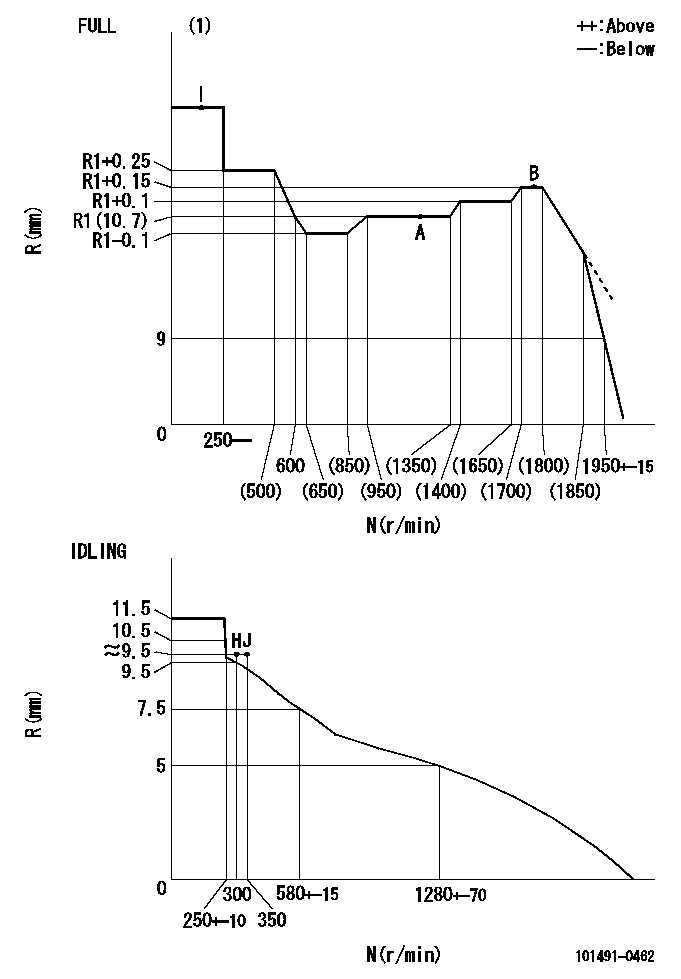
N:Pump speed
R:Rack position (mm)
(1)Torque cam stamping: T1
----------
T1=D60
----------
----------
T1=D60
----------
Speed control lever angle

F:Full speed
I:Idle
(1)Stopper bolt set position 'H'
----------
----------
a=5.5deg+-5deg b=36deg+-3deg
----------
----------
a=5.5deg+-5deg b=36deg+-3deg
Stop lever angle
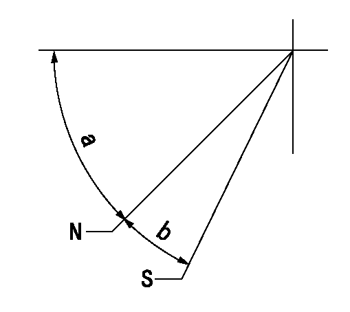
N:Pump normal
S:Stop the pump.
----------
----------
a=45deg+-5deg b=29deg+-5deg
----------
----------
a=45deg+-5deg b=29deg+-5deg
0000001501 ACS

(A) Set screw
(B) Push rod 1
(C) Push rod 2
(D) Cover
1. Aneroid compensator unit adjustment
(1)Select the push rod 2 to obtain L2.
(2)Screw in (A) to obtain L1.
2. Adjustment when mounting the governor.
(1)Set the speed of the pump to N1 r/min and fix the control lever at the full set position.
(2)Screw in the aneroid compensator to obtain the performance shown in the graph above.
(3)As there is hysterisis, measure when the absolute pressure drops.
(4)Hysterisis must not exceed rack position = h1.
----------
N1=1050r/min L1=(5)mm L2=11+-0.5mm h1=0.15mm
----------
Ra=R1(10.7)mm Rb=R1-0.45mm Pa=95.5+-5.3kPa(716+-40mmHg) Pb=70.1+-0.7kPa(526+-5mmHg) Q1=58.1cm3/1000st Q2=(44.5)+-1.6cm3/1000st
----------
N1=1050r/min L1=(5)mm L2=11+-0.5mm h1=0.15mm
----------
Ra=R1(10.7)mm Rb=R1-0.45mm Pa=95.5+-5.3kPa(716+-40mmHg) Pb=70.1+-0.7kPa(526+-5mmHg) Q1=58.1cm3/1000st Q2=(44.5)+-1.6cm3/1000st
Timing setting

(1)Pump vertical direction
(2)Position of gear mark 'CC' at No 1 cylinder's beginning of injection
(3)B.T.D.C.: aa
(4)-
----------
aa=17deg
----------
a=(90deg)
----------
aa=17deg
----------
a=(90deg)
Information:
(1) 7S7144 Spring for valves (new): Length under test force ... 44.86 mm (1.766 in.)Test force ... 257 25 N (57.7 4.5 lb.)Use again minimum load at length under test force ... 217 N (48.83 lb.)Length of spring at valve open position ... 32.28 mm (1.271 in.)Use again minimum load at valve open position ... 658 N (148.5 lb.)Free length after test ... 52.07 mm (2.05 in.)Outside diameter ... 35.21 mm (1.386 in.)Spring must not be bent more than ... 1.82 mm (.072 in.)(2) Height to top of valve guide ... 22.23 0.25 mm (.875 .010 in.)(3) Diameter of valve stem (new) ... 9.441 0.008 mm (.3717 .0003 in.) Use again minimum diameter ... 9.408 mm (.3704 in.)Bore in valve guide with guide installed in the head.Minimum permissible (new) ... 9.456 mm (.3723 in.)Maximum permissible (worn) ... 9.581 mm (.3772 in.)(4) Valve lip thickness: 6N9916 Exhaust ValveUse again minimum ... 2.69 mm (.106 in.)6N9915 Intake ValveUse again minimum ... 2.44 mm (.096 in.)(5) Diameter of valve head: Exhaust valve ... 48.16 0.13 mm (1.896 .005 in.)Intake valve ... 51.31 0.13 mm (2.020 .005 in.)(6) Angle of valve face ... 29 1/4 1/4° (7) Depth of bore in head for valve seat insert ... 12.28 0.13 mm (.483 .005 in.)(8) Diameter of valve seat insert for exhaust valve ... 50.889 0.013 mm (2.0035 .0005 in.) Bore in head for valve seat insert for exhaust valve ... 50.813 0.030 mm (2.0005 .0012 in.)Diameter of valve seat insert for intake valve ... 52.032 0.013 mm (2.0485 .0005 in.)Bore in head for valve seat insert for intake valve ... 51.956 0.030 mm (2.0455 .0012 in.)(9) Angle of face of valve seat insert ... 30 1°(10) Maximum permissible width of valve seat (intake and exhaust) ... 1.93 mm (.076 in.) Minimum permissible width of valve seat (intake and exhaust) ... 1.14 mm (.045 in.)(11) Dimension from top of closed valve to face of head: Minimum permissible dimension for 6N9916 Exhaust Valve ... 0.66 mm (.026 in.)Minimum permissible dimension for 6N9915 Intake Valve ... 0.15 mm (.006 in.)(12) Outside diameter of the face of the valve seat insert: Exhaust seat ... 46.02 mm (1.812 in.)Maximum permissible, exhaust seat ... 47.29 mm (1.862 in.)Intake seat ... 49.28 mm (1.940 in.)Maximum permissible, intake seat ... 50.55 mm (1.990 in.)(13) Angle to grind seat face of the insert to get a reduction of maximum seat diameter ... 15°Procedure to Check Intake Valve Timing
1. Check the No. 1 intake valve clearance with the engine stopped. The valve clearance must be 0.30 to 0.46 mm (.012 to .018 in.). If the valve clearance is not in this range, adjust the clearance to .038 mm (.015 in.).2. Mark Top Center Position of the crankshaft on the vibration damper or pulley.3. Use a dial indicator to measure the intake valve movement.4. Rotate the crankshaft in the direction of normal
1. Check the No. 1 intake valve clearance with the engine stopped. The valve clearance must be 0.30 to 0.46 mm (.012 to .018 in.). If the valve clearance is not in this range, adjust the clearance to .038 mm (.015 in.).2. Mark Top Center Position of the crankshaft on the vibration damper or pulley.3. Use a dial indicator to measure the intake valve movement.4. Rotate the crankshaft in the direction of normal