Information injection-pump assembly
ZEXEL
101491-0310
1014910310
ISUZU
8944415710
8944415710

Rating:
Cross reference number
ZEXEL
101491-0310
1014910310
ISUZU
8944415710
8944415710
Zexel num
Bosch num
Firm num
Name
Calibration Data:
Adjustment conditions
Test oil
1404 Test oil ISO4113 or {SAEJ967d}
1404 Test oil ISO4113 or {SAEJ967d}
Test oil temperature
degC
40
40
45
Nozzle and nozzle holder
105780-8140
Bosch type code
EF8511/9A
Nozzle
105780-0000
Bosch type code
DN12SD12T
Nozzle holder
105780-2080
Bosch type code
EF8511/9
Opening pressure
MPa
17.2
Opening pressure
kgf/cm2
175
Injection pipe
Outer diameter - inner diameter - length (mm) mm 6-2-600
Outer diameter - inner diameter - length (mm) mm 6-2-600
Tester oil delivery pressure
kPa
157
157
157
Tester oil delivery pressure
kgf/cm2
1.6
1.6
1.6
Direction of rotation (viewed from drive side)
Right R
Right R
Injection timing adjustment
Direction of rotation (viewed from drive side)
Right R
Right R
Injection order
1-3-4-2
Pre-stroke
mm
3.4
3.35
3.45
Rack position
Point A R=A
Point A R=A
Beginning of injection position
Drive side NO.1
Drive side NO.1
Difference between angles 1
Cal 1-3 deg. 90 89.5 90.5
Cal 1-3 deg. 90 89.5 90.5
Difference between angles 2
Cal 1-4 deg. 180 179.5 180.5
Cal 1-4 deg. 180 179.5 180.5
Difference between angles 3
Cyl.1-2 deg. 270 269.5 270.5
Cyl.1-2 deg. 270 269.5 270.5
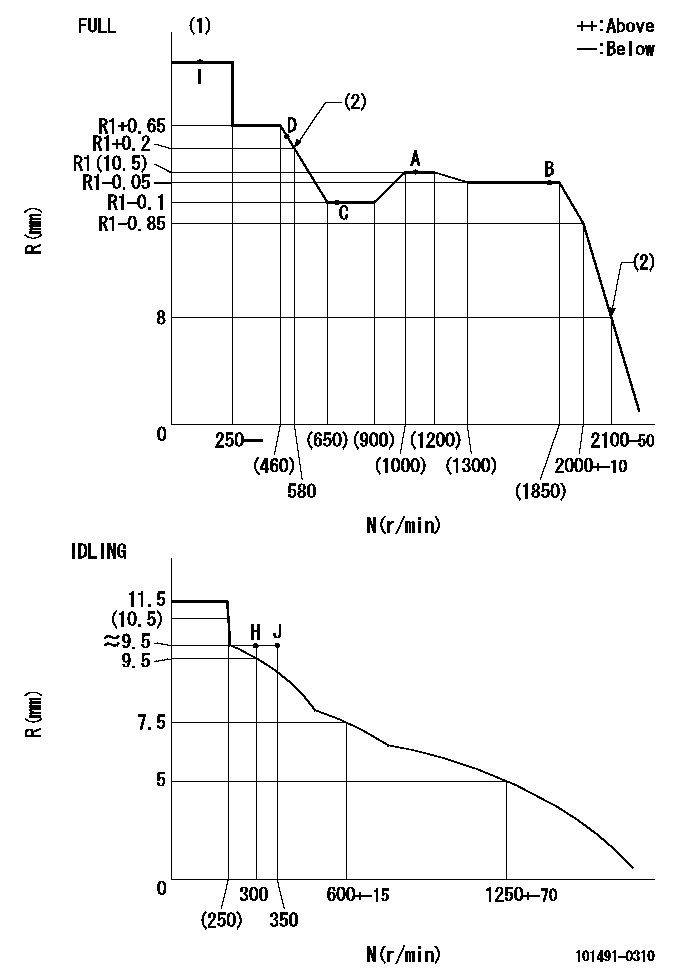
Injection quantity adjustment
Adjusting point
-
Rack position
10.5
Pump speed
r/min
1100
1100
1100
Average injection quantity
mm3/st.
59.2
57.6
60.8
Max. variation between cylinders
%
0
-3.5
3.5
Basic
*
Fixing the rack
*
Standard for adjustment of the maximum variation between cylinders
*
Injection quantity adjustment_02
Adjusting point
-
Rack position
9.8+-0.5
Pump speed
r/min
300
300
300
Average injection quantity
mm3/st.
9.5
8
11
Max. variation between cylinders
%
0
-10
10
Fixing the rack
*
Standard for adjustment of the maximum variation between cylinders
*
Remarks
Adjust only variation between cylinders; adjust governor according to governor specifications.
Adjust only variation between cylinders; adjust governor according to governor specifications.
Injection quantity adjustment_03
Adjusting point
A
Rack position
R1(10.5)
Pump speed
r/min
1100
1100
1100
Average injection quantity
mm3/st.
59.2
58.2
60.2
Basic
*
Fixing the lever
*
Injection quantity adjustment_04
Adjusting point
B
Rack position
R1-0.05
Pump speed
r/min
1800
1800
1800
Average injection quantity
mm3/st.
61.3
58.1
64.5
Fixing the lever
*
Injection quantity adjustment_05
Adjusting point
C
Rack position
R1-0.1
Pump speed
r/min
700
700
700
Average injection quantity
mm3/st.
43.5
40.3
46.7
Fixing the lever
*
Injection quantity adjustment_06
Adjusting point
D
Rack position
R1+0.5
Pump speed
r/min
500
500
500
Average injection quantity
mm3/st.
46.1
42.1
50.1
Fixing the lever
*
Injection quantity adjustment_07
Adjusting point
I
Rack position
-
Pump speed
r/min
100
100
100
Average injection quantity
mm3/st.
66
50
82
Fixing the lever
*
Timer adjustment
Pump speed
r/min
1650--
Advance angle
deg.
0
0
0
Remarks
Start
Start
Timer adjustment_02
Pump speed
r/min
1600
Advance angle
deg.
0.6
Timer adjustment_03
Pump speed
r/min
1800
Advance angle
deg.
3
2.5
3.5
Timer adjustment_04
Pump speed
r/min
1900
Advance angle
deg.
4.5
4
5
Timer adjustment_05
Pump speed
r/min
-
Advance angle
deg.
5
5
5
Remarks
Measure the actual speed, stop
Measure the actual speed, stop
Test data Ex:
Governor adjustment
N:Pump speed
R:Rack position (mm)
(1)Torque cam stamping: T1
(2)The torque cam setting and high idle must be set when speed is increasing from low to high (because of hysterisis).
----------
T1=A73
----------
----------
T1=A73
----------
Speed control lever angle
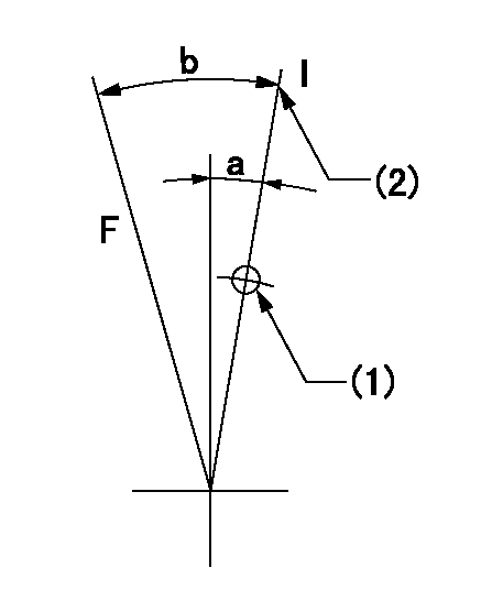
F:Full speed
I:Idle
(1)Use the hole at R = aa
(2)Stopper bolt set position 'H'
----------
aa=50mm
----------
a=29deg+-5deg b=41deg+-3deg
----------
aa=50mm
----------
a=29deg+-5deg b=41deg+-3deg
0000001501 MICRO SWITCH
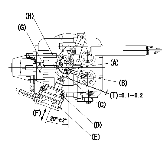
(A) Cam fixing bolt
(B) Screw B
(C) Cam (select)
(D) Microswitch fixing bolt
(E) Microswitch
(F) Adjusting direction
(G) Idle adjusting bolt
(H) Full speed adjusting bolt
(T) Distance
Adjustment of the micro-switch
1. Adjustment specifications
(1)Full side switch ON position
When a thickness gauge is inserted between the speed lever and the full speed adjusting bolt and the speed lever is moved from the idle side to the full side.
Confirm no continuity using a thickness gauge t = 0.3.
Confirm no continuity using a thickness gauge t = 0.1.
(2)Idle side switch ON.
When a thickness gauge is inserted between the speed lever and the idle adjusting bolt and the speed lever is moved from the full side to the idle side.
Confirm no continuity using a thickness gauge t = 1.1.
Confirm no continuity using a thickness gauge t = 0.5.
2. Procedures for adjustment
(1)Standard position for Cam (159226-8100), stamping mark M, is explained in above illustration.
(2)Fix the microswitch body in the position shown in the figure above. (The microswitch is free.)
(3)Full side adjustment
Adjust using screw B to satisfy the adjustment specifications (1) above.
(4)Idle side confirmation
Move the speed lever from the full side to the idle side and confirm the above adjustment specification (2).
(5)When the idle side is not as specified, replace the cam (stamping S or L) and repeat adjustment from procedure 2.(2) above.
----------
----------
----------
----------
Timing setting

(1)Pump vertical direction
(2)Position of gear mark 'CC' at No 1 cylinder's beginning of injection
(3)B.T.D.C.: aa
(4)-
----------
aa=15deg
----------
a=(100deg)
----------
aa=15deg
----------
a=(100deg)
Information:
Features
Benefits
All critical engineering changes and updates included
Improved reliability and performance
Worldwide availability through Cat parts distribution system
Customer access regardless of location
Off-the-shelf availability
Downtime reduced through exchange product
Same-as-new Caterpillar warranty
Consistent support
Coverage Chart
Reman PN
New PN
Part Name
20R1298
3594090
INJECTOR GP - FUEL
20R1299
3494080
INJECTOR GP - FUEL
20R1301
3594020
INJECTOR GP - FUEL
20R1302
3594040
INJECTOR GP - FUEL
20R1303
3594070
INJECTOR GP - FUEL
20R1304
3597434
INJECTOR GP - FUEL
20R1308
3594050
INJECTOR GP - FUEL
20R1302
3594040
INJECTOR GP - FUEL
20R1317
3809889
INJECTOR GP - FUEL
20R1318
3674293
INJECTOR GP - FUEL
20R3247
3920225
INJECTOR GP - FUEL
20R3607
3820709
INJECTOR GP - FUEL
20R3608
3820745
INJECTOR GP – FUEL
20R3815
3689171
PUMP GP – FUEL INJ
20R3816
3689172
PUMP GP – FUEL INJ
20R3817
3689173
PUMP GP – FUEL INJ
Core Acceptance
The following Core Acceptance Criteria are available supporting these products. All the latest Core Acceptance Criteria guidelines can be found on the Reman Dealer Extranet at https://catreman.cat.com/cac
SELD0226 Unit Injectors Electronic
SELD0023 Fuel Pump & Governor Groups
Warranty
Please consult the appropriate warranty statement for your area by going to warranty.cat.com.
Core Management
Please refer to the Caterpillar Core Management Information System (CMIS 2) related to the parts information application that describes all Reman part/Core Acceptability Family (CAF) and other related information. Also, refer to other CMIS 2 inquiry applications such as: Dealer Customer Profile, Inspection Reason Codes, Inspection Line Inquiry, Dealer Add Charges, Dealer Entitlement Activity, Dealer CCR Inquiry, Dealer CCR Entry, Dealer Shipment Processing, Dealer Process Packaging Grief and Reporting. This information is available to all dealers worldwide that have been converted to CMIS 2.
Please go to the Reman web site https://catreman.cat.com for the latest policy and procedural updates that are available to all dealers worldwide explaining policy and procedural information such as “Policy and Core Management” -SELD0122; “Core Management Systems and Operations Procedures” -SELD0040; “Reman Core Return Packaging Instructions And Guidelines” -SELD0300; and “Shipping Instructions” SELD0039.
If you have any questions regarding Reman Core Management or Core Management Systems (CMIS2), feel free to call your Corinth Dealer Service Representative toll free at (800) 537-2928.
Contact Information:
For assistance with technical questions, call the Reman Technical Hot Line also toll free at (888) 88-REMAN or use our e-mail address--Reman_Help.
Global Dealer Solutions Network Parts Technical Support Team Toll Free -North America: 1-877-228-2420 International: +1-309-266-4421 Electronic Requests: Send via Microsoft Customer Relationship Management (MSCRM). For access and tutorial information: https://gdsn.cat.com/mscrm
, CATERPILLAR, BUILT FOR IT, their respective logos, “Caterpillar Yellow” and the ”Power Edge” trade dress, as well as corporate and product identity used herein, are trademarks of Caterpillar and may not be used without permission.
The information contained herein is intended for circulation only to Caterpillar and dealer employees whose duties require knowledge of such reports and is intended exclusively for their information and