Information injection-pump assembly
BOSCH
9 400 614 277
9400614277
ZEXEL
101491-0303
1014910303
ISUZU
8944041064
8944041064

Rating:
Service parts 101491-0303 INJECTION-PUMP ASSEMBLY:
1.
_
6.
COUPLING PLATE
7.
COUPLING PLATE
8.
_
9.
_
10.
NOZZLE AND HOLDER ASSY
11.
Nozzle and Holder
12.
Open Pre:MPa(Kqf/cm2)
13.
NOZZLE-HOLDER
14.
NOZZLE
15.
NOZZLE SET
Cross reference number
BOSCH
9 400 614 277
9400614277
ZEXEL
101491-0303
1014910303
ISUZU
8944041064
8944041064
Zexel num
Bosch num
Firm num
Name
101491-0303
9 400 614 277
8944041064 ISUZU
INJECTION-PUMP ASSEMBLY
4BC2 * K
4BC2 * K
Calibration Data:
Adjustment conditions
Test oil
1404 Test oil ISO4113 or {SAEJ967d}
1404 Test oil ISO4113 or {SAEJ967d}
Test oil temperature
degC
40
40
45
Nozzle and nozzle holder
105780-8140
Bosch type code
EF8511/9A
Nozzle
105780-0000
Bosch type code
DN12SD12T
Nozzle holder
105780-2080
Bosch type code
EF8511/9
Opening pressure
MPa
17.2
Opening pressure
kgf/cm2
175
Injection pipe
Outer diameter - inner diameter - length (mm) mm 6-2-600
Outer diameter - inner diameter - length (mm) mm 6-2-600
Tester oil delivery pressure
kPa
157
157
157
Tester oil delivery pressure
kgf/cm2
1.6
1.6
1.6
Direction of rotation (viewed from drive side)
Right R
Right R
Injection timing adjustment
Direction of rotation (viewed from drive side)
Right R
Right R
Injection order
1-3-4-2
Pre-stroke
mm
3.4
3.35
3.45
Beginning of injection position
Drive side NO.1
Drive side NO.1
Difference between angles 1
Cal 1-3 deg. 90 89.5 90.5
Cal 1-3 deg. 90 89.5 90.5
Difference between angles 2
Cal 1-4 deg. 180 179.5 180.5
Cal 1-4 deg. 180 179.5 180.5
Difference between angles 3
Cyl.1-2 deg. 270 269.5 270.5
Cyl.1-2 deg. 270 269.5 270.5
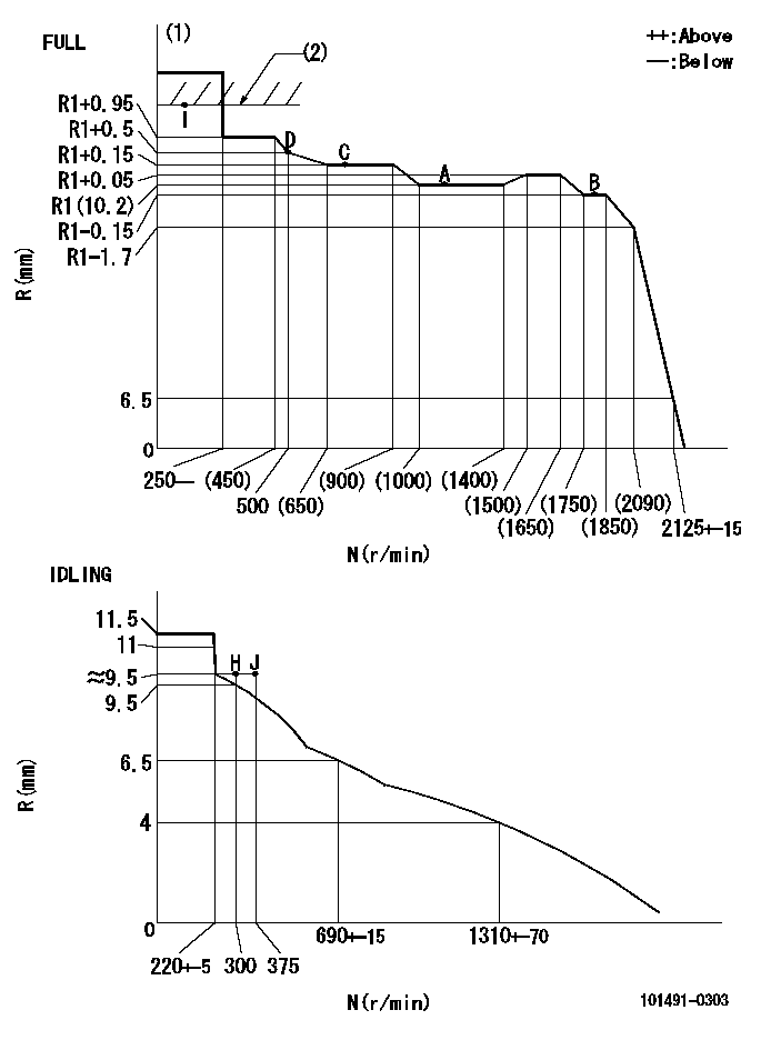
Injection quantity adjustment
Adjusting point
-
Rack position
10.2
Pump speed
r/min
1100
1100
1100
Average injection quantity
mm3/st.
50.7
49.1
52.3
Max. variation between cylinders
%
0
-4
4
Basic
*
Fixing the rack
*
Standard for adjustment of the maximum variation between cylinders
*
Injection quantity adjustment_02
Adjusting point
-
Rack position
9.7+-0.5
Pump speed
r/min
300
300
300
Average injection quantity
mm3/st.
9.5
8
11
Max. variation between cylinders
%
0
-10
10
Fixing the rack
*
Standard for adjustment of the maximum variation between cylinders
*
Remarks
Adjust only variation between cylinders; adjust governor according to governor specifications.
Adjust only variation between cylinders; adjust governor according to governor specifications.
Injection quantity adjustment_03
Adjusting point
A
Rack position
R1(10.2)
Pump speed
r/min
1100
1100
1100
Average injection quantity
mm3/st.
50.7
49.7
51.7
Basic
*
Fixing the lever
*
Injection quantity adjustment_04
Adjusting point
B
Rack position
R1-0.15
Pump speed
r/min
1800
1800
1800
Average injection quantity
mm3/st.
48.3
45.1
51.5
Fixing the lever
*
Injection quantity adjustment_05
Adjusting point
C
Rack position
R1+0.15
Pump speed
r/min
700
700
700
Average injection quantity
mm3/st.
41.8
38.6
45
Fixing the lever
*
Injection quantity adjustment_06
Adjusting point
D
Rack position
R1+0.5
Pump speed
r/min
500
500
500
Average injection quantity
mm3/st.
37
33
41
Fixing the lever
*
Injection quantity adjustment_07
Adjusting point
I
Rack position
-
Pump speed
r/min
100
100
100
Average injection quantity
mm3/st.
56
51
61
Fixing the lever
*
Rack limit
*
Timer adjustment
Pump speed
r/min
1650--
Advance angle
deg.
0
0
0
Remarks
Start
Start
Timer adjustment_02
Pump speed
r/min
1600
Advance angle
deg.
0.6
Timer adjustment_03
Pump speed
r/min
1800
Advance angle
deg.
3
2.5
3.5
Timer adjustment_04
Pump speed
r/min
1900
Advance angle
deg.
4.5
4
5
Timer adjustment_05
Pump speed
r/min
-
Advance angle
deg.
5
5
5
Remarks
Measure the actual speed, stop
Measure the actual speed, stop
Test data Ex:
Governor adjustment
N:Pump speed
R:Rack position (mm)
(1)Torque cam stamping: T1
(2)RACK LIMIT
----------
T1=B22
----------
----------
T1=B22
----------
Speed control lever angle
F:Full speed
I:Idle
(1)Stopper bolt set position 'H'
(2)Speed = aa, rack position = bb (lever angle with microswitch ON)
(3)After installing the microswitch, confirm that the speed lever moves smoothly and that and that the full speed lever angle = d.
----------
aa=1150r/min bb=8.1mm
----------
a=0deg+-5deg b=46.5deg+-3deg c=27deg+-3deg d=(51deg)+-3deg
----------
aa=1150r/min bb=8.1mm
----------
a=0deg+-5deg b=46.5deg+-3deg c=27deg+-3deg d=(51deg)+-3deg
Timing setting

(1)Pump vertical direction
(2)Position of gear mark 'CC' at No 1 cylinder's beginning of injection
(3)B.T.D.C.: aa
(4)-
----------
aa=16deg
----------
a=(100deg)
----------
aa=16deg
----------
a=(100deg)
Information:
For serial number specific information, please see SISWEB.
Features and Benefits
Cat Reman products offer excellent value to customers. Customers who want fast repair turn-around, superior quality and reliability, and lower repair costs will benefit from the use of these remanufactured products. Cat Reman parts provide immediate, off-the-shelf availability at a fraction of the new price.
Features Benefits
All critical engineering changes and updates included
Improved reliability and performance
Worldwide availability through Cat® parts distribution system
Customer access regardless of location
Backed by Caterpillar parts warranty
Consistent support
Core Acceptance
Core Acceptance Criteria for Cat Reman parts is simple, visual, and requires no special tools. Please consult the applicable Core Acceptance Criteria for each product for complete details. Core Acceptance Criteria can be found at catreman.cat.com/cac.
Unit Injectors Electronic - SELD0226-01
Warranty
Please consult the appropriate Caterpillar parts warranty statement for your area.
Core Management
Please refer to the Cat Core Management Information System (CMIS 2) Parts Information application describing all Cat Reman part/CAF and related information. Also refer to other CMIS 2 inquiry applications such as Customer Profiles, Inspection Reason Codes, Inspection Line Inquiry, Add Charge Information, Entitlement Activity, Entitlement Inquiry, CCR Inquiry, CCR Entry, Shipment Processing; Process Packaging Grief; and Reporting to properly manage core returns and monitor inspection performance. This information will be available to all dealers worldwide after your CMIS 2 conversion date. In the meantime, please continue to use the current CMIS Entitlement Parts Inquiry Screen describing the list of parts in a Core Acceptability Family (CAF) and related part number detail.
For the latest updates of Reman Policies and Core Management (SELD0122), Core Management Systems & Operations Procedures (SELD0040), and Shipping Instructions (SELD0039), go to the Reman Dealer website https://catreman.cat.com. If you have any questions regarding core return processing, feel free to call Corinth toll free at (800) 537-2928. Outside the US please refer to the Core section of the Reman website for appropriate contact information for your region.
For assistance with technical questions, call the Peoria Reman Technical Help Line also toll free at (888) 88-REMAN (outside the US call non-toll free +1-309-494-4342), or use our E-mail address, Reman_Help.
Contact Information:
Global Dealer Solutions Network
Parts Technical Support Team
Toll Free - North America: 1-877-228-2420
International: +1-309-266-4421
Electronic Requests: Send via Microsoft Customer Relationship Management (MSCRM)
For access and tutorial information: https://gdsn.cat.com/mscrm
Have questions with 101491-0303?
Group cross 101491-0303 ZEXEL
Isuzu
101491-0303
9 400 614 277
8944041064
INJECTION-PUMP ASSEMBLY
4BC2
4BC2