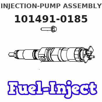
Information injection-pump assembly
BOSCH
9 400 614 272
9400614272
ZEXEL
101491-0185
1014910185
ISUZU
5156013735
5156013735
Rating:
Service parts 101491-0185 INJECTION-PUMP ASSEMBLY:
1.
_
6.
COUPLING PLATE
7.
COUPLING PLATE
8.
_
9.
_
11.
Nozzle and Holder
12.
Open Pre:MPa(Kqf/cm2)
18.1(185)

15.
NOZZLE SET
Cross reference number
BOSCH
9 400 614 272
9400614272
ZEXEL
101491-0185
1014910185
ISUZU
5156013735
5156013735
Zexel num
Bosch num
Firm num
Name
101491-0185
9 400 614 272
5156013735 ISUZU
INJECTION-PUMP ASSEMBLY
4BC2 K 14BC INJECTION PUMP ASSY PE4A,5A, PE
4BC2 K 14BC INJECTION PUMP ASSY PE4A,5A, PE
Calibration Data:
Adjustment conditions
Test oil
1404 Test oil ISO4113 or {SAEJ967d}
1404 Test oil ISO4113 or {SAEJ967d}
Test oil temperature
degC
40
40
45
Nozzle and nozzle holder
105780-8140
Bosch type code
EF8511/9A
Nozzle
105780-0000
Bosch type code
DN12SD12T
Nozzle holder
105780-2080
Bosch type code
EF8511/9
Opening pressure
MPa
17.2
Opening pressure
kgf/cm2
175
Injection pipe
Outer diameter - inner diameter - length (mm) mm 6-2-600
Outer diameter - inner diameter - length (mm) mm 6-2-600
Tester oil delivery pressure
kPa
157
157
157
Tester oil delivery pressure
kgf/cm2
1.6
1.6
1.6
Direction of rotation (viewed from drive side)
Right R
Right R
Injection timing adjustment
Direction of rotation (viewed from drive side)
Right R
Right R
Injection order
1-3-4-2
Pre-stroke
mm
3.4
3.35
3.45
Beginning of injection position
Drive side NO.1
Drive side NO.1
Difference between angles 1
Cal 1-3 deg. 90 89.5 90.5
Cal 1-3 deg. 90 89.5 90.5
Difference between angles 2
Cal 1-4 deg. 180 179.5 180.5
Cal 1-4 deg. 180 179.5 180.5
Difference between angles 3
Cyl.1-2 deg. 270 269.5 270.5
Cyl.1-2 deg. 270 269.5 270.5
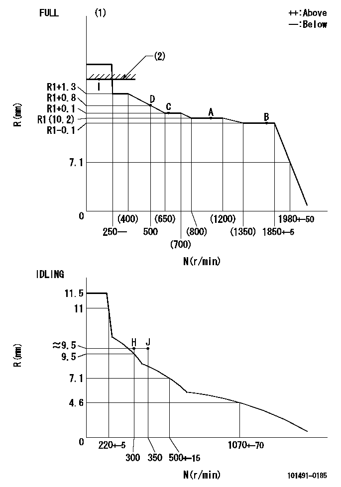
Injection quantity adjustment
Adjusting point
-
Rack position
10.2
Pump speed
r/min
1100
1100
1100
Average injection quantity
mm3/st.
49.2
47.6
50.8
Max. variation between cylinders
%
0
-4
4
Basic
*
Fixing the rack
*
Standard for adjustment of the maximum variation between cylinders
*
Injection quantity adjustment_02
Adjusting point
H
Rack position
9.9+-0.5
Pump speed
r/min
300
300
300
Average injection quantity
mm3/st.
9.5
8
11
Max. variation between cylinders
%
0
-14
14
Fixing the rack
*
Standard for adjustment of the maximum variation between cylinders
*
Remarks
Adjust only variation between cylinders; adjust governor according to governor specifications.
Adjust only variation between cylinders; adjust governor according to governor specifications.
Injection quantity adjustment_03
Adjusting point
A
Rack position
R1(10.2)
Pump speed
r/min
1100
1100
1100
Average injection quantity
mm3/st.
49.2
48.2
50.2
Basic
*
Fixing the lever
*
Injection quantity adjustment_04
Adjusting point
B
Rack position
R1-0.1
Pump speed
r/min
1800
1800
1800
Average injection quantity
mm3/st.
46.5
43.3
49.7
Fixing the lever
*
Injection quantity adjustment_05
Adjusting point
C
Rack position
R1+0.1
Pump speed
r/min
700
700
700
Average injection quantity
mm3/st.
39.8
36.6
43
Fixing the lever
*
Injection quantity adjustment_06
Adjusting point
D
Rack position
R1+0.8
Pump speed
r/min
500
500
500
Average injection quantity
mm3/st.
40.7
36.7
44.7
Fixing the lever
*
Injection quantity adjustment_07
Adjusting point
I
Rack position
-
Pump speed
r/min
100
100
100
Average injection quantity
mm3/st.
57.5
52.5
62.5
Fixing the lever
*
Rack limit
*
Timer adjustment
Pump speed
r/min
1650--
Advance angle
deg.
0
0
0
Remarks
Start
Start
Timer adjustment_02
Pump speed
r/min
1600
Advance angle
deg.
0.6
Timer adjustment_03
Pump speed
r/min
1800
Advance angle
deg.
3
2.5
3.5
Timer adjustment_04
Pump speed
r/min
1900
Advance angle
deg.
4.5
4
5
Timer adjustment_05
Pump speed
r/min
-
Advance angle
deg.
5
5
5
Remarks
Measure the actual speed, stop
Measure the actual speed, stop
Test data Ex:
Governor adjustment
N:Pump speed
R:Rack position (mm)
(1)Torque cam stamping: T1
(2)RACK LIMIT
----------
T1=55
----------
----------
T1=55
----------
Speed control lever angle

F:Full speed
I:Idle
(1)Stopper bolt set position 'H'
----------
----------
a=5.5deg+-5deg b=40deg+-3deg
----------
----------
a=5.5deg+-5deg b=40deg+-3deg
Stop lever angle
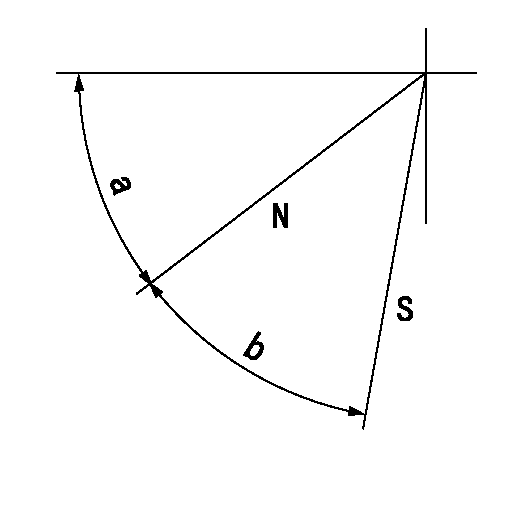
N:Pump normal
S:Stop the pump.
----------
----------
a=45deg+-5deg b=40deg+-5deg
----------
----------
a=45deg+-5deg b=40deg+-5deg
Timing setting

(1)Pump vertical direction
(2)Position of gear mark 'CC' at No 1 cylinder's beginning of injection
(3)B.T.D.C.: aa
(4)-
----------
aa=16deg
----------
a=(100deg)
----------
aa=16deg
----------
a=(100deg)
Information:
Fuel Injection Nozzles
Disassembly of Fuel Injection Nozzles
Inspection of Fuel Injection Nozzles
Check each fuel injection nozzle for the following, and if defects are found, repair or replace the fuel injection nozzle.(1) Inspection of injection start pressure(a) Install each fuel injection nozzle on the nozzle tester, and move the handle up and down to release air.(b) Operate the handle of the tester at a rate of about 1 stroke per second, and read the indication on the pressure gage. The indication rises slowly, and the indicator oscillates during spraying. To obtain the injection start pressure value, read the indication when the indicator starts to oscillate.
Inspection of fuel injection nozzle valve opening(c) If the injection start pressure deviates significantly from the standard value, disassemble the fuel injection nozzle, and make an adjustment by changing the washer thickness. 0.1 mm [0.0039 in.] thickness of shims will change the injection pressure 0.98 Mpa (10 kgf/cm2 [142 psi]. The shims are available in 10 different thickness from 1.25 to 1.70 mm [0.0492 to 0.0669 in.] increment of 0.05 mm [0.0020 in.]
Never tap the tip of the nozzle tip when removing the nozzle tip.
Replacement of fuel injection nozzle tip(2) Inspection of fuel injection nozzle spray pattern(a) When inspecting each fuel injection nozzle with the nozzle tester, also check the nozzle for clogs, spray pattern and leakage.(b) Make sure that the fuel is sprayed straight from the nozzle when the handle of the tester is operated at a rate of about 1 stroke per second.
Inspection of spray pattern of fuel injection nozzle(3) Cleaning and replacement of faulty nozzles(a) Loosen the nozzle retaining nut, remove the nozzle tip, and clean the needle valve and body.
Never tap the tip of the nozzle tip when removing the nozzle tip.
(b) Use a fresh cleaning solution to clean the needle valve and body. After cleaning, assemble the needle valve and body in clean diesel fuel. The needle valve and body are precision finished. Handle them carefully, and do not change the combination of parts.
Cleaning of fuel injection nozzle tip(c) Tighten the nozzle retaining nut on the nozzle tip to the specified torque.(d) If the spray pattern is still not acceptable after adjustment and cleaning, replace the nozzle tip. (a) Never touch the sliding surface of the needle valve.(b) When installing a new nozzle tip, remove the seal film (synthetic resin film), and slide needle valve in the nozzle in a fresh cleaning solution to remove anti-rust oil coating thoroughly from the new nozzleReassembly of Fuel Injection Nozzles
Fuel Filter
Disassembly and Inspection of Fuel Filter
Have questions with 101491-0185?
Group cross 101491-0185 ZEXEL
Isuzu
101491-0185
9 400 614 272
5156013735
INJECTION-PUMP ASSEMBLY
4BC2
4BC2