Information injection-pump assembly
BOSCH
9 400 614 265
9400614265
ZEXEL
101482-9322
1014829322
YANMAR
12990451500
12990451500
Rating:
Cross reference number
BOSCH
9 400 614 265
9400614265
ZEXEL
101482-9322
1014829322
YANMAR
12990451500
12990451500
Zexel num
Bosch num
Firm num
Name
101482-9322
9 400 614 265
12990451500 YANMAR
INJECTION-PUMP ASSEMBLY
4TNE92 K
4TNE92 K
Calibration Data:
Adjustment conditions
Test oil
1404 Test oil ISO4113 or {SAEJ967d}
1404 Test oil ISO4113 or {SAEJ967d}
Test oil temperature
degC
40
40
45
Nozzle and nozzle holder
105780-8140
Bosch type code
EF8511/9A
Nozzle
105780-0000
Bosch type code
DN12SD12T
Nozzle holder
105780-2080
Bosch type code
EF8511/9
Opening pressure
MPa
17.2
Opening pressure
kgf/cm2
175
Injection pipe
Outer diameter - inner diameter - length (mm) mm 6-2-600
Outer diameter - inner diameter - length (mm) mm 6-2-600
Overflow valve
131424-1520
Overflow valve opening pressure
kPa
157
123
191
Overflow valve opening pressure
kgf/cm2
1.6
1.25
1.95
Tester oil delivery pressure
kPa
157
157
157
Tester oil delivery pressure
kgf/cm2
1.6
1.6
1.6
Direction of rotation (viewed from drive side)
Right R
Right R
Injection timing adjustment
Direction of rotation (viewed from drive side)
Right R
Right R
Injection order
1-3-4-2
Pre-stroke
mm
2.8
2.75
2.85
Beginning of injection position
Drive side NO.1
Drive side NO.1
Difference between angles 1
Cal 1-3 deg. 90 89.5 90.5
Cal 1-3 deg. 90 89.5 90.5
Difference between angles 2
Cal 1-4 deg. 180 179.5 180.5
Cal 1-4 deg. 180 179.5 180.5
Difference between angles 3
Cyl.1-2 deg. 270 269.5 270.5
Cyl.1-2 deg. 270 269.5 270.5
Injection quantity adjustment
Adjusting point
A
Rack position
8
Pump speed
r/min
1225
1225
1225
Average injection quantity
mm3/st.
34.9
33.9
35.9
Max. variation between cylinders
%
0
-2.5
2.5
Basic
*
Fixing the lever
*
Injection quantity adjustment_02
Adjusting point
-
Rack position
7.5+-0.5
Pump speed
r/min
390
390
390
Average injection quantity
mm3/st.
10
9
11
Max. variation between cylinders
%
0
-15
15
Fixing the rack
*
Remarks
Adjust only variation between cylinders; adjust governor according to governor specifications.
Adjust only variation between cylinders; adjust governor according to governor specifications.
Injection quantity adjustment_03
Adjusting point
D
Rack position
10.2++
Pump speed
r/min
100
100
100
Average injection quantity
mm3/st.
35
35
45
Fixing the lever
*
Rack limit
*
Test data Ex:
Governor adjustment
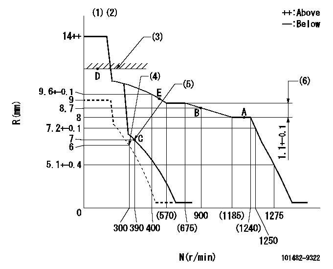
N:Pump speed
R:Rack position (mm)
(1)Target notch: K
(2)Tolerance for racks not indicated: +-0.05mm.
(3)RACK LIMIT
(4)Set idle sub-spring
(5)Main spring setting
(6)Rack difference between N = N1 and N = N2
----------
K=8 N1=1225r/min N2=650r/min
----------
----------
K=8 N1=1225r/min N2=650r/min
----------
Speed control lever angle

F:Full speed
I:Idle
(1)Stopper bolt setting
----------
----------
a=6deg+-5deg b=28deg+-5deg
----------
----------
a=6deg+-5deg b=28deg+-5deg
Stop lever angle
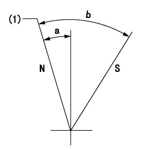
N:Pump normal
S:Stop the pump.
(1)Normal
----------
----------
a=7deg+-5deg b=53deg+-5deg
----------
----------
a=7deg+-5deg b=53deg+-5deg
Timing setting

(1)Pump vertical direction
(2)Position of camshaft's key groove at No 1 cylinder's beginning of injection
(3)-
(4)-
----------
----------
a=(50deg)
----------
----------
a=(50deg)
Information:
Removal of idler gearCamshaft End Play
Measure the camshaft end play, and, if the limit value is exceeded, replace the thrust plate.
Measurement of camshaft end playReversal of Crankcase
Gently lay the crankcase on its side, then turn the crankcase upside down.
Resting the crankcase with the oil pan on the bottom can cause the oil pan to crack.
Reversal of crankcaseRemoval of Oil Pan And Oil Pan Gasket
(1) Unscrew the oil pan mounting bolts, and detach the oil pan.(2) Remove the oil pan gasket.
Removal of oil pan and oil gasketRemoval of Oil Pump
Unscrew the oil pump set bolt, and pull out the oil pump.
Removal of oil pumpRemoval of Camshaft
Removal of camshaft(1) Position the camshaft gear so that the two lightening holes are on the top and bottom, then remove the thrust plate mounting bolts using the socket.(2) Pull out the camshaft from the crankcase.
Be careful not to damage the cams and bearing sections on the camshaft.
Removal of Front Plate
Removal of front plateUnscrew the front plate mounting bolts, and dismount the front plate (together with the injection pump) from the crankcase.Pistons, Connecting Rods, Crankshaft and Crankcase
When replacing the crankcase, remove all accessories (relief valve and others) carefully from the crankcase, and reinstall them on a new crankcase.Laying Crankcase on Its Side
Gently lay the crankcase on its side.
Laying crankcase on its sideMeasurement of Connecting Rod End Play
(1) Measure the clearance between the big-end of each connecting rod and the crankshaft (end play) with feeler gages. (2) If the measured clearance exceeds the limit value, replace the connecting rod.
Measurement of connecting rod End PlayRemoval of Connecting Rod Caps
(1) On each connecting rod and cap, put a mark indicating its cylinder No.(2) Remove the connecting rod caps.(3) For each removed connecting rod bearing (lower half), indicate the piston No. from which it was removed and the upper/lower identification. Be careful not to damage the bearings. Arrange the removed bearings in such a way that they can be reinstalled in their original positions during reassembly.
Removal of connecting rod capPreparation For Removal of Pistons
If carbon deposits are present at the upper sections of the cylinders, remove the carbon deposits with sandpaper and a cloth to facilitate piston removal.
Preparation for removal of pistonRemoval of Pistons
(1) Turn the crankshaft to bring the piston to be removed to the top dead center.(2) Using the wooden handle of a hammer, push the connecting rod on the cap contacting surface to remove the piston and connecting rod assembly from the top side of the cylinder.
Removal of pistonRemoval of Piston Ring
Using the piston ring pliers, remove the piston rings
Removal of piston ringRemoval of Piston Pins
Removal of piston pin(1) Using the snap ring pliers, remove the snap rings.(2) Pull out the piston pin, and separate the piston from the connecting rod.(3) If the piston pin cannot be remove easily, heat the piston with a piston heater or in hot water.Reversal of Crankcase
Gently stand the crankcase so that the oil pan mounting side faces up.
Reversal of crankcaseMeasurement of Crankshaft End Play
(1) With a dial gage positioned
Have questions with 101482-9322?
Group cross 101482-9322 ZEXEL
Dpico
Nissan-Diesel
Yanmar
101482-9322
9 400 614 265
12990451500
INJECTION-PUMP ASSEMBLY
4TNE92
4TNE92