Information injection-pump assembly
ZEXEL
101482-9151
1014829151
NISSAN-DIESEL
1679090316
1679090316

Rating:
Cross reference number
ZEXEL
101482-9151
1014829151
NISSAN-DIESEL
1679090316
1679090316
Zexel num
Bosch num
Firm num
Name
101482-9151
1679090316 NISSAN-DIESEL
INJECTION-PUMP ASSEMBLY
BD30 * K
BD30 * K
Calibration Data:
Adjustment conditions
Test oil
1404 Test oil ISO4113 or {SAEJ967d}
1404 Test oil ISO4113 or {SAEJ967d}
Test oil temperature
degC
40
40
45
Nozzle and nozzle holder
105780-8140
Bosch type code
EF8511/9A
Nozzle
105780-0000
Bosch type code
DN12SD12T
Nozzle holder
105780-2080
Bosch type code
EF8511/9
Opening pressure
MPa
17.2
Opening pressure
kgf/cm2
175
Injection pipe
Outer diameter - inner diameter - length (mm) mm 6-2-600
Outer diameter - inner diameter - length (mm) mm 6-2-600
Overflow valve
131424-1520
Overflow valve opening pressure
kPa
157
123
191
Overflow valve opening pressure
kgf/cm2
1.6
1.25
1.95
Tester oil delivery pressure
kPa
157
157
157
Tester oil delivery pressure
kgf/cm2
1.6
1.6
1.6
Direction of rotation (viewed from drive side)
Right R
Right R
Injection timing adjustment
Direction of rotation (viewed from drive side)
Right R
Right R
Injection order
1-3-4-2
Pre-stroke
mm
3.2
3.15
3.25
Beginning of injection position
Drive side NO.1
Drive side NO.1
Difference between angles 1
Cal 1-3 deg. 90 89.5 90.5
Cal 1-3 deg. 90 89.5 90.5
Difference between angles 2
Cal 1-4 deg. 180 179.5 180.5
Cal 1-4 deg. 180 179.5 180.5
Difference between angles 3
Cyl.1-2 deg. 270 269.5 270.5
Cyl.1-2 deg. 270 269.5 270.5
Injection quantity adjustment
Adjusting point
B
Rack position
10.5
Pump speed
r/min
800
800
800
Average injection quantity
mm3/st.
42.1
41.1
43.1
Max. variation between cylinders
%
0
-3.5
3.5
Basic
*
Fixing the lever
*
Injection quantity adjustment_02
Adjusting point
-
Rack position
9+-0.5
Pump speed
r/min
425
425
425
Average injection quantity
mm3/st.
8
6
10
Max. variation between cylinders
%
0
-10
10
Fixing the rack
*
Remarks
Adjust only variation between cylinders; adjust governor according to governor specifications.
Adjust only variation between cylinders; adjust governor according to governor specifications.
Injection quantity adjustment_03
Adjusting point
D
Rack position
10.7++
Pump speed
r/min
100
100
100
Average injection quantity
mm3/st.
62
62
72
Fixing the lever
*
Rack limit
*
Test data Ex:
Governor adjustment
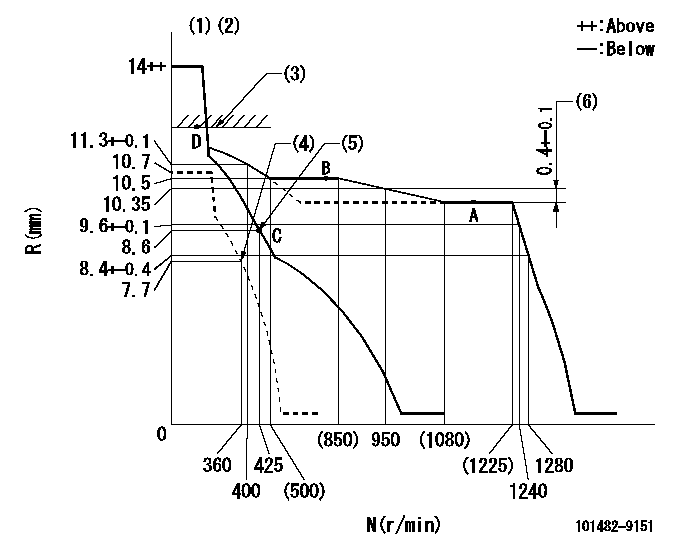
N:Pump speed
R:Rack position (mm)
(1)Target notch: K
(2)Tolerance for racks not indicated: +-0.05mm.
(3)RACK LIMIT
(4)Set idle sub-spring
(5)Main spring setting
(6)Rack difference between N = N1 and N = N2
----------
K=12 N1=1150r/min N2=800r/min
----------
----------
K=12 N1=1150r/min N2=800r/min
----------
Speed control lever angle
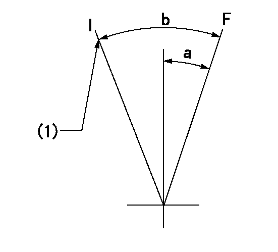
F:Full speed
I:Idle
(1)Stopper bolt setting
----------
----------
a=10deg+-5deg b=18deg+-5deg
----------
----------
a=10deg+-5deg b=18deg+-5deg
Stop lever angle

N:Pump normal
S:Stop the pump.
(1)Normal
----------
----------
a=12deg+-5deg b=53deg+-5deg
----------
----------
a=12deg+-5deg b=53deg+-5deg
Timing setting

(1)Pump vertical direction
(2)Position of gear mark 'ZZ' at No 1 cylinder's beginning of injection
(3)B.T.D.C.: aa
(4)-
----------
aa=16deg
----------
a=(100deg)
----------
aa=16deg
----------
a=(100deg)
Information:
Disassembly and Reassembly of General Parts
Oil seals
When driving oil seals into place, follow the instructions below: Driving Seals into Housing:(a) Place the seal lip correctly. Make sure it is not damaged.(b) Before driving a seal into place, apply a light coat of grease to the periphery of the seal that fits into the housing.(c) Use a driving tool like the one shown in the illustration that is specifically designed for the purpose. The tool can properly guide the lip and hold evenly the top of the seal when it is tapped, so it allows the seal to be driven straight down. Do not use hammers on bare seals as seal will be damaged.
Oil seal driving tool Driving Seals onto Shaft:(a) Coat the seal lip with grease.(b) Use seal guide like the one shown in the illustration when the shaft has steps, splines, threads or keyways.
Oil seal guideO-Rings
Use a guide when it is necessary to move O-rings over steps, splines, threads or keyways to install them. Apply a light coat of grease to O-rings before fitting them.
O-ring guideBearings
(1) When driving bearing into place, be sure to tap the race that is being fitted. (If the inner race is being fitted, tap the inner race. Likewise, if it is the outer race that is being fitted, tap the outer race.)Use fitting tools like the ones in the illustration that are appropriate for inner or outer races.
Bearing fitting tool(2) Bearings are best fitted using a press as shock loads and errors can be minimized.
Fitting bearing using a pressLock Plates
Always bend lock plates properly. The illustration on the right show some of typical lock plates being bent properly and improperly.
Typical lock plates with good and bad bendsSplit Pins and Spring Pins
As a rule, all split pins must be replaced with new ones after each removal. It is also important to bend split pins properly. Spring pins must be driven into place completely.
Have questions with 101482-9151?
Group cross 101482-9151 ZEXEL
Nissan-Diesel
Nissan-Diesel
Nissan-Diesel
Nissan-Diesel
101482-9151
1679090316
INJECTION-PUMP ASSEMBLY
BD30
BD30