Information injection-pump assembly
ZEXEL
101482-9081
1014829081
NISSAN-DIESEL
1679090309
1679090309
Rating:
Cross reference number
ZEXEL
101482-9081
1014829081
NISSAN-DIESEL
1679090309
1679090309
Zexel num
Bosch num
Firm num
Name
101482-9081
1679090309 NISSAN-DIESEL
INJECTION-PUMP ASSEMBLY
BD30 * K
BD30 * K
Calibration Data:
Adjustment conditions
Test oil
1404 Test oil ISO4113 or {SAEJ967d}
1404 Test oil ISO4113 or {SAEJ967d}
Test oil temperature
degC
40
40
45
Nozzle and nozzle holder
105780-8140
Bosch type code
EF8511/9A
Nozzle
105780-0000
Bosch type code
DN12SD12T
Nozzle holder
105780-2080
Bosch type code
EF8511/9
Opening pressure
MPa
17.2
Opening pressure
kgf/cm2
175
Injection pipe
Outer diameter - inner diameter - length (mm) mm 6-2-600
Outer diameter - inner diameter - length (mm) mm 6-2-600
Overflow valve
131424-1520
Overflow valve opening pressure
kPa
157
123
191
Overflow valve opening pressure
kgf/cm2
1.6
1.25
1.95
Tester oil delivery pressure
kPa
157
157
157
Tester oil delivery pressure
kgf/cm2
1.6
1.6
1.6
Direction of rotation (viewed from drive side)
Right R
Right R
Injection timing adjustment
Direction of rotation (viewed from drive side)
Right R
Right R
Injection order
1-3-4-2
Pre-stroke
mm
3.2
3.15
3.25
Beginning of injection position
Drive side NO.1
Drive side NO.1
Difference between angles 1
Cal 1-3 deg. 90 89.5 90.5
Cal 1-3 deg. 90 89.5 90.5
Difference between angles 2
Cal 1-4 deg. 180 179.5 180.5
Cal 1-4 deg. 180 179.5 180.5
Difference between angles 3
Cyl.1-2 deg. 270 269.5 270.5
Cyl.1-2 deg. 270 269.5 270.5
Injection quantity adjustment
Adjusting point
A
Rack position
10.7
Pump speed
r/min
1200
1200
1200
Average injection quantity
mm3/st.
59.9
58.9
60.9
Max. variation between cylinders
%
0
-3.5
3.5
Basic
*
Fixing the lever
*
Injection quantity adjustment_02
Adjusting point
-
Rack position
9.2+-0.5
Pump speed
r/min
450
450
450
Average injection quantity
mm3/st.
8
6
10
Max. variation between cylinders
%
0
-10
10
Fixing the rack
*
Remarks
Adjust only variation between cylinders; adjust governor according to governor specifications.
Adjust only variation between cylinders; adjust governor according to governor specifications.
Injection quantity adjustment_03
Adjusting point
D
Rack position
10.9++
Pump speed
r/min
100
100
100
Average injection quantity
mm3/st.
62
62
72
Fixing the lever
*
Rack limit
*
Test data Ex:
Governor adjustment
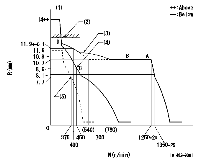
N:Pump speed
R:Rack position (mm)
(1)Target notch: K
(2)RACK LIMIT
(3)No set force
(4)Main spring setting
(5)Set idle sub-spring
----------
K=13
----------
----------
K=13
----------
Speed control lever angle
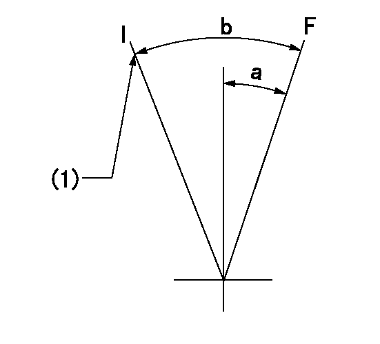
F:Full speed
I:Idle
(1)Stopper bolt setting
----------
----------
a=10deg+-5deg b=19deg+-5deg
----------
----------
a=10deg+-5deg b=19deg+-5deg
Stop lever angle

N:Pump normal
S:Stop the pump.
(1)Normal
----------
----------
a=12deg+-5deg b=53deg+-5deg
----------
----------
a=12deg+-5deg b=53deg+-5deg
Timing setting

(1)Pump vertical direction
(2)Position of camshaft's key groove at No 1 cylinder's beginning of injection
(3)-
(4)-
----------
----------
a=(60deg)
----------
----------
a=(60deg)
Information:
Injection timing adjustment shim
Adjusting injection timing(3) Alternative Adjustment/Inspection ProcedureThe injection timing adjustment/inspection procedure in which the delivery valve is removed allows the flow of fuel to be verified clearly, but removing the delivery valve can allow dirt to enter the fuel system. With the procedure described below, it is possible to check the injection timing without removing the delivery valve.(a) Disconnect injection pipe No. 1 from the nozzle holder.
Disconnecting injection pipe No. 1(b) Slowly turn the crankshaft clockwise, and note the position of the IT mark at the point in time when fuel emerges from the end of the pipe. The timing indicated by the IT mark is retarded by approximately 1° relative to the actual injection timing, so this 1° difference must be taken into account in the shim selection. Air-bleed the fuel system before turning the crankshaft. 4. Injectors
4.1 Removal
Removing and installing injectors1 Fuel injection pipe2 Injector holder3 Injector4 Gasket
The fuel injection pipe nut should be tightened to the specified torque using a tool specially designed for the purpose.
4.2 Inspection and AdjustmentCheck each injector for the following points. If the result is not satisfactory, either repair or replace it according to conditions.(1) Injector Valve Opening Pressure(a) Install an injector on an injector tester. Move the handle up and down repeatedly to remove air from the injector.(b) While observing the pressure gauge, operate the handle at a rate of approximately one stroke per second. Record the reading.
Testing injector valve opening pressure The needle of the gauge moves slowly toward the higher pressure side and then wobbles while injection is taking place. Injector valve opening pressure corresponds to a pressure at which the gauge needle starts wobbling.(c) If the reading on the gauge does not correspond to the specified injector valve opening pressure of 21.6+10 MPa {220+100kgf/cm2} (3130+1420 psi), disassemble the injector and replace the washer with one of proper thickness.(d) A change of 0.1 mm (0.004 in.) in the washer thickness yields a change of 1.5 MPa {15 kgf/cm2} (213 psi).
Never expose any part of your body to the spray of fuel injected from the injector.
Adjusting injector valve opening pressure(2) Spray Condition(a) Operate the injector tester handle at a rate of approximately one stroke per second.(b) The spray pattern A in the drawing on the right is normal while all the other patterns are abnormal. The spray may be coarse and narrow, and some fuel may remain on the nozzle hole after injection. However, these conditions are typically observed during tests on a tester and thus do not indicate abnormal operation of the injector.(c) Operate the tester handle at a rate of approximately four to six strokes per second. The injector can be considered normal if fuel is injected evenly and at correct angles (see drawing) from all the four nozzle holes and fine atomization of fuel is observed in all sprays.
Inspecting spray condition(3) Leakage from InjectorsUse the injector tester to maintain a pressure 1-2 MPa {10-20 kgf/cm2} (142-285 psi) lower than the specified injector valve opening
Have questions with 101482-9081?
Group cross 101482-9081 ZEXEL
Daewoo
Nissan-Diesel
Nissan-Diesel
Nissan-Diesel
Nissan-Diesel
Nissan-Diesel
101482-9081
1679090309
INJECTION-PUMP ASSEMBLY
BD30
BD30