Information injection-pump assembly
ZEXEL
101482-9051
1014829051
Rating:
Service parts 101482-9051 INJECTION-PUMP ASSEMBLY:
1.
_
5.
AUTOM. ADVANCE MECHANIS
6.
COUPLING PLATE
8.
_
9.
_
11.
Nozzle and Holder
16600-T9300
12.
Open Pre:MPa(Kqf/cm2)
21.6{220}

15.
NOZZLE SET
Cross reference number
ZEXEL
101482-9051
1014829051
Zexel num
Bosch num
Firm num
Name
101482-9051
INJECTION-PUMP ASSEMBLY
Calibration Data:
Adjustment conditions
Test oil
1404 Test oil ISO4113 or {SAEJ967d}
1404 Test oil ISO4113 or {SAEJ967d}
Test oil temperature
degC
40
40
45
Nozzle and nozzle holder
105780-8140
Bosch type code
EF8511/9A
Nozzle
105780-0000
Bosch type code
DN12SD12T
Nozzle holder
105780-2080
Bosch type code
EF8511/9
Opening pressure
MPa
17.2
Opening pressure
kgf/cm2
175
Injection pipe
Outer diameter - inner diameter - length (mm) mm 6-2-600
Outer diameter - inner diameter - length (mm) mm 6-2-600
Overflow valve opening pressure
kPa
157
123
191
Overflow valve opening pressure
kgf/cm2
1.6
1.25
1.95
Tester oil delivery pressure
kPa
157
157
157
Tester oil delivery pressure
kgf/cm2
1.6
1.6
1.6
Direction of rotation (viewed from drive side)
Right R
Right R
Injection timing adjustment
Direction of rotation (viewed from drive side)
Right R
Right R
Injection order
1-3-4-2
Pre-stroke
mm
2.8
2.75
2.85
Beginning of injection position
Drive side NO.1
Drive side NO.1
Difference between angles 1
Cal 1-3 deg. 90 89.5 90.5
Cal 1-3 deg. 90 89.5 90.5
Difference between angles 2
Cal 1-4 deg. 180 179.5 180.5
Cal 1-4 deg. 180 179.5 180.5
Difference between angles 3
Cyl.1-2 deg. 270 269.5 270.5
Cyl.1-2 deg. 270 269.5 270.5
Injection quantity adjustment
Adjusting point
A
Rack position
10.5
Pump speed
r/min
1000
1000
1000
Average injection quantity
mm3/st.
61.6
60.6
62.6
Max. variation between cylinders
%
0
-2.5
2.5
Basic
*
Fixing the lever
*
Boost pressure
kPa
64
64
Boost pressure
mmHg
480
480
Injection quantity adjustment_02
Adjusting point
B
Rack position
R1-0.7
Pump speed
r/min
500
500
500
Average injection quantity
mm3/st.
32.8
28.8
36.8
Max. variation between cylinders
%
0
-4
4
Fixing the lever
*
Boost pressure
kPa
0
0
0
Boost pressure
mmHg
0
0
0
Injection quantity adjustment_03
Adjusting point
-
Rack position
8+-0.5
Pump speed
r/min
300
300
300
Average injection quantity
mm3/st.
10
8
12
Max. variation between cylinders
%
0
-15
15
Fixing the rack
*
Boost pressure
kPa
0
0
0
Boost pressure
mmHg
0
0
0
Remarks
Adjust only variation between cylinders; adjust governor according to governor specifications.
Adjust only variation between cylinders; adjust governor according to governor specifications.
Injection quantity adjustment_04
Adjusting point
D
Rack position
13.3+-0.
5
Pump speed
r/min
100
100
100
Average injection quantity
mm3/st.
81
71
91
Fixing the lever
*
Rack limit
*
Boost compensator adjustment
Pump speed
r/min
500
500
500
Rack position
R1-0.7
Boost pressure
kPa
12
10.7
13.3
Boost pressure
mmHg
90
80
100
Boost compensator adjustment_02
Pump speed
r/min
500
500
500
Rack position
R1(10.5)
Boost pressure
kPa
53.3
53.3
53.3
Boost pressure
mmHg
400
400
400
Test data Ex:
Governor adjustment
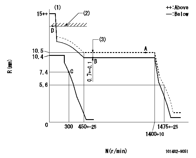
N:Pump speed
R:Rack position (mm)
(1)Target notch: K
(2)RACK LIMIT
(3)Boost compensator stroke (at N = N1)
----------
K=6 N1=500r/min
----------
----------
K=6 N1=500r/min
----------
Speed control lever angle

F:Full speed
I:Idle
(1)Stopper bolt setting
----------
----------
a=9deg+-5deg b=33deg+-5deg
----------
----------
a=9deg+-5deg b=33deg+-5deg
Stop lever angle

N:Pump normal
S:Stop the pump.
----------
----------
a=16.5deg+-5deg b=50deg+-5deg
----------
----------
a=16.5deg+-5deg b=50deg+-5deg
0000001501 GOV FULL LOAD ADJUSTMENT

Title1:Full load stopper adjustment
Title2:Governor set speed
LABEL1:Distinguishing
LABEL2:Pump speed (r/min)
LABEL3:Ave. injection quantity (mm3/st)
LABEL4:Max. var. bet. cyl.
LABEL5:Remarks
LABEL6:Distinguishing
LABEL7:Governor set speed (r/min)
LABEL8:Maximum no-load speed (r/min)
LABEL9:Remarks
(1)Adjustment conditions are the same as those for measuring injection quantity.
(2)At high idle rack position L
----------
L=5.6mm
----------
a1=A a2=B a3=C a4=- r1=1100r/min r2=1000r/min r3=1000r/min r4=- Q1=68.8+-1mm3/st Q2=61.6+-1mm3/st Q3=56.1+-1mm3/st Q4=- c1=+-2.5% c2=+-2.5% c3=+-2.5% c4=- a5=28 a6=27 a7=26 a8=25 a9=24 a10=23 a11=22 a12=21 a13=20 a14=19 a15=- r5=1400r/min r6=1350r/min r7=1300r/min r8=1250r/min r9=1200r/min r10=1150r/min r11=1100r/min r12=1050r/min r13=1000r/min r14=950r/min r15=- R5=1475+-25r/min R6=1450+-33r/min R7=1395+-32r/min R8=1340+-31r/min R9=1290+-30r/min R10=1235+-28r/min R11=1180+-25r/min R12=1130+-26r/min R13=1075+-25r/min R14=1020+-23r/min R15=-
----------
L=5.6mm
----------
a1=A a2=B a3=C a4=- r1=1100r/min r2=1000r/min r3=1000r/min r4=- Q1=68.8+-1mm3/st Q2=61.6+-1mm3/st Q3=56.1+-1mm3/st Q4=- c1=+-2.5% c2=+-2.5% c3=+-2.5% c4=- a5=28 a6=27 a7=26 a8=25 a9=24 a10=23 a11=22 a12=21 a13=20 a14=19 a15=- r5=1400r/min r6=1350r/min r7=1300r/min r8=1250r/min r9=1200r/min r10=1150r/min r11=1100r/min r12=1050r/min r13=1000r/min r14=950r/min r15=- R5=1475+-25r/min R6=1450+-33r/min R7=1395+-32r/min R8=1340+-31r/min R9=1290+-30r/min R10=1235+-28r/min R11=1180+-25r/min R12=1130+-26r/min R13=1075+-25r/min R14=1020+-23r/min R15=-
Timing setting

(1)Pump vertical direction
(2)Position of gear's standard threaded hole at No 1 cylinder's beginning of injection (position of gear's 'M' mark)
(3)B.T.D.C.: aa
(4)-
----------
aa=14deg
----------
a=(60deg)
----------
aa=14deg
----------
a=(60deg)
Information:
1. Determining Overhaul Timing
The timing of engine overhauls should be determined primarily in accordance with reductions in compression pressure. A reduction in compression pressure may be accompanied by one or more of the following externally observable symptoms:(a) Reduced power(b) Increased fuel consumption(c) Increased engine-oil consumption(d) Increased blowby gas through breather (possibly owing to wear on cylinder liners and piston rings)(e) Gas leakage (possibly owing to poor seating of intake and exhaust valves)(f) Starting problems(g) Increased engine noise(h) Abnormal exhaust-gas color after engine warmupAlthough these symptoms can be caused by a reduction in compression pressure, they can be caused also by other problems that are not related to engine deterioration. Notably, symptoms (b) and (f) may be affected significantly by the injection pump's injection rate, by the injection timing, by plunger wear, by injector defects, and/or by the battery, starter, and other electrical equipment. Symptoms (d) should be given special attention since a decrease in compression pressure owing to wear on the cylinder liners and piston rings is one of the most obvious signs that the engine needs an overhaul. It is essential, however, to measure the compression pressure in each cylinder and to use the results as the primary criteria for making a decision to overhaul the engine.2. Measuring Compression Pressure
2.1 Preparation for InspectionPerform the following checks before starting the inspection.(1) Make sure the engine oil, air cleaner, starter, and battery are normal.(2) Make sure the engine is warm.2.2 Inspection(1) Move the control lever to the stop position.(2) Remove all glow plugs, then connect the Compression Gauge Adapter (ST333060) and compression gauge to the cylinder whose compression pressure is to be checked.(3) Crank the engine using the starter until the needle of the compression gauge stops moving, then read the pressure indication.(4) If the measurement is lower than the specified limit, perform an overhaul.
(a) Measure the compression pressure of every cylinder. Measuring the compression pressures of two or three cylinders and simply assuming the compression pressures of the other cylinders is dangerous.(b) The compression pressure varies with the engine speed, so it is important to take all measurements with the same engine speed.
Unit: MPa {kgf/cm2} (psi) Take measurements with an engine speed of 240 min-1.
Compression gauge and adapter
Measuring compression pressure
(a) It is important to measure compression pressures regularly and to keep track of changes in them.(b) During the engine's run-in period and after an overhaul, the compression pressures will increase slightly as the piston rings, valve seats, and other parts fit snugly in position. The pressures will then decrease as parts wear.
3. Troubleshooting
3.1 OverviewDiesel-engine fault symptoms tend to have multiple causes, which influence each other. Consequently, it is often difficult to locate a fault based on the symptoms. Particular care is required when diagnosing faults related to the injection pump, injectors, and compression pressures since such faults may produce the same symptoms.For the above-mentioned reasons, the inspection sequences in the troubleshooting charts on the following pages start with items where the likelihood of a fault is greatest with
Have questions with 101482-9051?
Group cross 101482-9051 ZEXEL
Daewoo
Nissan-Diesel
Nissan-Diesel
101482-9051
INJECTION-PUMP ASSEMBLY