Information injection-pump assembly
ZEXEL
101482-9030
1014829030
Rating:
Cross reference number
ZEXEL
101482-9030
1014829030
Zexel num
Bosch num
Firm num
Name
101482-9030
INJECTION-PUMP ASSEMBLY
Calibration Data:
Adjustment conditions
Test oil
1404 Test oil ISO4113 or {SAEJ967d}
1404 Test oil ISO4113 or {SAEJ967d}
Test oil temperature
degC
40
40
45
Nozzle and nozzle holder
105780-8140
Bosch type code
EF8511/9A
Nozzle
105780-0000
Bosch type code
DN12SD12T
Nozzle holder
105780-2080
Bosch type code
EF8511/9
Opening pressure
MPa
17.2
Opening pressure
kgf/cm2
175
Injection pipe
Outer diameter - inner diameter - length (mm) mm 6-2-600
Outer diameter - inner diameter - length (mm) mm 6-2-600
Overflow valve opening pressure
kPa
157
123
191
Overflow valve opening pressure
kgf/cm2
1.6
1.25
1.95
Tester oil delivery pressure
kPa
157
157
157
Tester oil delivery pressure
kgf/cm2
1.6
1.6
1.6
Direction of rotation (viewed from drive side)
Right R
Right R
Injection timing adjustment
Direction of rotation (viewed from drive side)
Right R
Right R
Injection order
1-3-4-2
Pre-stroke
mm
2.8
2.75
2.85
Beginning of injection position
Drive side NO.1
Drive side NO.1
Difference between angles 1
Cal 1-3 deg. 90 89.5 90.5
Cal 1-3 deg. 90 89.5 90.5
Difference between angles 2
Cal 1-4 deg. 180 179.5 180.5
Cal 1-4 deg. 180 179.5 180.5
Difference between angles 3
Cyl.1-2 deg. 270 269.5 270.5
Cyl.1-2 deg. 270 269.5 270.5
Injection quantity adjustment
Adjusting point
A
Rack position
10.5
Pump speed
r/min
1000
1000
1000
Average injection quantity
mm3/st.
61.6
60.6
62.6
Max. variation between cylinders
%
0
-2.5
2.5
Basic
*
Fixing the lever
*
Boost pressure
kPa
84
84
Boost pressure
mmHg
630
630
Injection quantity adjustment_02
Adjusting point
B
Rack position
9.5
Pump speed
r/min
500
500
500
Average injection quantity
mm3/st.
28.3
24.3
32.3
Max. variation between cylinders
%
0
-4
4
Fixing the lever
*
Boost pressure
kPa
0
0
0
Boost pressure
mmHg
0
0
0
Injection quantity adjustment_03
Adjusting point
-
Rack position
8+-0.5
Pump speed
r/min
300
300
300
Average injection quantity
mm3/st.
10
8
12
Max. variation between cylinders
%
0
-15
15
Fixing the rack
*
Boost pressure
kPa
0
0
0
Boost pressure
mmHg
0
0
0
Remarks
Adjust only variation between cylinders; adjust governor according to governor specifications.
Adjust only variation between cylinders; adjust governor according to governor specifications.
Injection quantity adjustment_04
Adjusting point
D
Rack position
13.3+-0.
5
Pump speed
r/min
100
100
100
Average injection quantity
mm3/st.
81
71
91
Fixing the lever
*
Rack limit
*
Boost compensator adjustment
Pump speed
r/min
500
500
500
Rack position
9.5
Boost pressure
kPa
12
10.7
13.3
Boost pressure
mmHg
90
80
100
Boost compensator adjustment_02
Pump speed
r/min
500
500
500
Rack position
10.5
Boost pressure
kPa
70.6
63.9
77.3
Boost pressure
mmHg
530
480
580
Test data Ex:
Governor adjustment
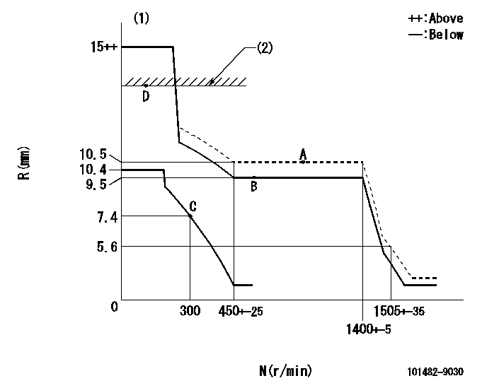
N:Pump speed
R:Rack position (mm)
(1)Target notch: K
(2)RACK LIMIT
----------
K=10
----------
----------
K=10
----------
Speed control lever angle

F:Full speed
I:Idle
(1)Stopper bolt setting
----------
----------
a=11deg+-5deg b=27deg+-5deg
----------
----------
a=11deg+-5deg b=27deg+-5deg
Stop lever angle

N:Pump normal
S:Stop the pump.
----------
----------
a=16.5deg+-5deg b=50deg+-5deg
----------
----------
a=16.5deg+-5deg b=50deg+-5deg
0000001501 GOV FULL LOAD ADJUSTMENT

Title1:Full load stopper adjustment
Title2:Governor set speed
LABEL1:Distinguishing
LABEL2:Pump speed (r/min)
LABEL3:Ave. injection quantity (mm3/st)
LABEL4:Max. var. bet. cyl.
LABEL5:Remarks
LABEL6:Distinguishing
LABEL7:Governor set speed (r/min)
LABEL8:Maximum no-load speed (r/min)
LABEL9:Remarks
(1)Adjustment conditions are the same as those for measuring injection quantity.
(2)At high idle rack position L
----------
L=5.6mm
----------
a1=A a2=B a3=- a4=- r1=1100r/min r2=1000r/min r3=- r4=- Q1=68.8+-1mm3/st Q2=61.6+-1mm3/st Q3=- Q4=- c1=+-2.5% c2=+-2.5% c3=- c4=- a5=28 a6=27 a7=26 a8=25 a9=24 a10=23 a11=22 a12=21 a13=20 a14=- a15=- r5=1400r/min r6=1350r/min r7=1300r/min r8=1250r/min r9=1200r/min r10=1150r/min r11=1100r/min r12=1050r/min r13=1000r/min r14=- r15=- R5=1505+-35r/min R6=1450+-33r/min R7=1395+-32r/min R8=1340+-31r/min R9=1290+-30r/min R10=1235+-28r/min R11=1180+-27r/min R12=1130+-26r/min R13=1075+-25r/min R14=- R15=-
----------
L=5.6mm
----------
a1=A a2=B a3=- a4=- r1=1100r/min r2=1000r/min r3=- r4=- Q1=68.8+-1mm3/st Q2=61.6+-1mm3/st Q3=- Q4=- c1=+-2.5% c2=+-2.5% c3=- c4=- a5=28 a6=27 a7=26 a8=25 a9=24 a10=23 a11=22 a12=21 a13=20 a14=- a15=- r5=1400r/min r6=1350r/min r7=1300r/min r8=1250r/min r9=1200r/min r10=1150r/min r11=1100r/min r12=1050r/min r13=1000r/min r14=- r15=- R5=1505+-35r/min R6=1450+-33r/min R7=1395+-32r/min R8=1340+-31r/min R9=1290+-30r/min R10=1235+-28r/min R11=1180+-27r/min R12=1130+-26r/min R13=1075+-25r/min R14=- R15=-
Timing setting

(1)Pump vertical direction
(2)Position of gear's standard threaded hole at No 1 cylinder's beginning of injection (position of gear's 'M' mark)
(3)B.T.D.C.: aa
(4)-
----------
aa=14deg
----------
a=(60deg)
----------
aa=14deg
----------
a=(60deg)
Information:
After the valve clearance on the valves for all cylinders has been adjusted, turn the crankshaft two or three times and make sure the valve clearance is correct.
Adjusting valve clearanceFUEL INJECTION TIMING
1. Preparation(1) Close the fuel filter valve.(2) Disconnect the No. 1 fuel injection pipe from the cylinder head and injection pump.(3) Remove No. 1 delivery valve holder from the injection pump. Remove the delivery valve and spring from the holder. Restore the delivery valve holder only to the injection pump.(4) Connect the fuel injection
Have questions with 101482-9030?
Group cross 101482-9030 ZEXEL
Daewoo
Nissan-Diesel
101482-9030
INJECTION-PUMP ASSEMBLY