Information injection-pump assembly
ZEXEL
101482-9000
1014829000

Rating:
Service parts 101482-9000 INJECTION-PUMP ASSEMBLY:
1.
_
5.
AUTOM. ADVANCE MECHANIS
6.
COUPLING PLATE
7.
COUPLING PLATE
8.
_
9.
_
11.
Nozzle and Holder
12.
Open Pre:MPa(Kqf/cm2)
21.6{220}
15.
NOZZLE SET
Cross reference number
ZEXEL
101482-9000
1014829000
Zexel num
Bosch num
Firm num
Name
Calibration Data:
Adjustment conditions
Test oil
1404 Test oil ISO4113 or {SAEJ967d}
1404 Test oil ISO4113 or {SAEJ967d}
Test oil temperature
degC
40
40
45
Nozzle and nozzle holder
105780-8140
Bosch type code
EF8511/9A
Nozzle
105780-0000
Bosch type code
DN12SD12T
Nozzle holder
105780-2080
Bosch type code
EF8511/9
Opening pressure
MPa
17.2
Opening pressure
kgf/cm2
175
Injection pipe
Outer diameter - inner diameter - length (mm) mm 6-2-600
Outer diameter - inner diameter - length (mm) mm 6-2-600
Overflow valve
131424-1120
Overflow valve opening pressure
kPa
137
103
171
Overflow valve opening pressure
kgf/cm2
1.4
1.05
1.75
Tester oil delivery pressure
kPa
157
157
157
Tester oil delivery pressure
kgf/cm2
1.6
1.6
1.6
Direction of rotation (viewed from drive side)
Right R
Right R
Injection timing adjustment
Direction of rotation (viewed from drive side)
Right R
Right R
Injection order
1-3-4-2
Pre-stroke
mm
1.5
1.45
1.55
Beginning of injection position
Governor side NO.1
Governor side NO.1
Difference between angles 1
Cal 1-3 deg. 90 89.5 90.5
Cal 1-3 deg. 90 89.5 90.5
Difference between angles 2
Cal 1-4 deg. 180 179.5 180.5
Cal 1-4 deg. 180 179.5 180.5
Difference between angles 3
Cyl.1-2 deg. 270 269.5 270.5
Cyl.1-2 deg. 270 269.5 270.5
Injection quantity adjustment
Adjusting point
A
Rack position
9.4
Pump speed
r/min
1000
1000
1000
Average injection quantity
mm3/st.
54
52.5
55.5
Max. variation between cylinders
%
0
-2
2
Basic
*
Fixing the lever
*
Injection quantity adjustment_02
Adjusting point
C
Rack position
7
Pump speed
r/min
250
250
250
Average injection quantity
mm3/st.
12
9
15
Max. variation between cylinders
%
0
-13
13
Fixing the lever
*
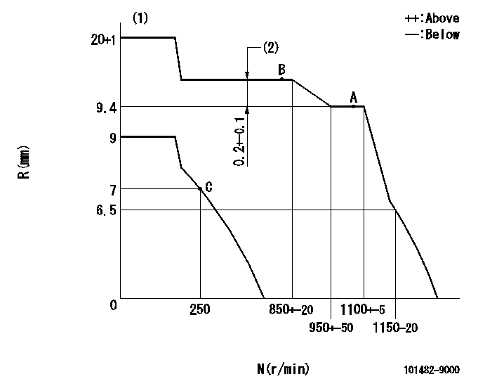
Test data Ex:
Governor adjustment

N:Pump speed
R:Rack position (mm)
(1)Target notch: K
(2)Torque control stroke
----------
K=12
----------
----------
K=12
----------
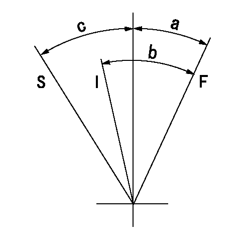
Speed control lever angle

F:Full speed
I:Idle
S:Stop
----------
----------
a=11deg+-5deg b=32deg+-5deg c=32deg+-3deg
----------
----------
a=11deg+-5deg b=32deg+-5deg c=32deg+-3deg
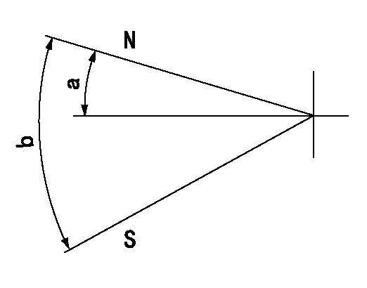
Stop lever angle

N:Pump normal
S:Stop the pump.
----------
----------
a=19deg+-5deg b=53deg+-5deg
----------
----------
a=19deg+-5deg b=53deg+-5deg
Information:
Putting cylinder head gasket6. Cylinder head installation Put the cylinder head in position on the cylinder block, making sure the guide bolts are all in alignment with their respective bolt holes in the head.
Installing cylinder head7. Cylinder head bolt tightening (1) Remove the guide bolts and install the bolts that hold the cylinder head to the cylinder block. (2) Tighten the bolts in the number sequence in two or three steps to the specified torque.
Tightening sequence8. Valve push rod installation (1) Put the valve push rod into position through the bore in the cylinder head.(2) Make sure the ball end of the push rod has been put into position over the top of the tappet.
Installing valve push rods9. Rocker shaft assembling (1) Install the rocker arms, brackets and springs on the rocker shaft. Secure the brackets to the shaft by tightening the bolts.(2) Make sure the rocker arms move freely.
Assembling rocker arms10. Rocker shaft assembly installation(1) Install the valve caps in position on the top of the valves. (2) Put the rocker shaft assembly in position on the cylinder head. Tighten the bolts that hold the rocker shaft assembly to the specified torque.
Installing rocker shaft assembly11. Valve clearance adjustment Make reference to "VALVE CLEARANCE" (page 159).
Adjusting valve clearance12. Rocker cover installation (1) Make sure the gasket is put on the rocker cover.(2) Tighten the bolts that hold the rocker cover to the specified torque.
Installing rocker coverAIR INLET SYSTEM AND EXHAUST SYSTEM
1. Air inlet cover installation Tighten the bolts that hold the air inlet cover to the specified torque. 2. Exhaust manifold installation Tighten the bolts that hold the exhaust manifold to the specified torque. FUEL SYSTEM
1. Fuel injection nozzle installation (1) Put the gasket on the nozzle. (2) Put the nozzle assembly in position in the cylinder head and tighten