Information injection-pump assembly
BOSCH
9 400 614 245
9400614245
ZEXEL
101482-4400
1014824400
ISUZU
8970155790
8970155790
Rating:
Service parts 101482-4400 INJECTION-PUMP ASSEMBLY:
1.
_
5.
AUTOM. ADVANCE MECHANIS
6.
COUPLING PLATE
8.
_
9.
_
11.
Nozzle and Holder
8-94122-262-5
12.
Open Pre:MPa(Kqf/cm2)
18.1{185}
15.
NOZZLE SET
Cross reference number
BOSCH
9 400 614 245
9400614245
ZEXEL
101482-4400
1014824400
ISUZU
8970155790
8970155790
Zexel num
Bosch num
Firm num
Name
101482-4400
9 400 614 245
8970155790 ISUZU
INJECTION-PUMP ASSEMBLY
4JB1 K 14BC INJECTION PUMP ASSY PE4A,5A, PE
4JB1 K 14BC INJECTION PUMP ASSY PE4A,5A, PE
Calibration Data:
Adjustment conditions
Test oil
1404 Test oil ISO4113 or {SAEJ967d}
1404 Test oil ISO4113 or {SAEJ967d}
Test oil temperature
degC
40
40
45
Nozzle and nozzle holder
105780-8140
Bosch type code
EF8511/9A
Nozzle
105780-0000
Bosch type code
DN12SD12T
Nozzle holder
105780-2080
Bosch type code
EF8511/9
Opening pressure
MPa
17.2
Opening pressure
kgf/cm2
175
Injection pipe
Outer diameter - inner diameter - length (mm) mm 6-2-600
Outer diameter - inner diameter - length (mm) mm 6-2-600
Tester oil delivery pressure
kPa
157
157
157
Tester oil delivery pressure
kgf/cm2
1.6
1.6
1.6
Direction of rotation (viewed from drive side)
Left L
Left L
Injection timing adjustment
Direction of rotation (viewed from drive side)
Left L
Left L
Injection order
1-3-4-2
Pre-stroke
mm
3.3
3.25
3.35
Beginning of injection position
Drive side NO.1
Drive side NO.1
Difference between angles 1
Cal 1-3 deg. 90 89.5 90.5
Cal 1-3 deg. 90 89.5 90.5
Difference between angles 2
Cal 1-4 deg. 180 179.5 180.5
Cal 1-4 deg. 180 179.5 180.5
Difference between angles 3
Cyl.1-2 deg. 270 269.5 270.5
Cyl.1-2 deg. 270 269.5 270.5
Injection quantity adjustment
Adjusting point
A
Rack position
9.5
Pump speed
r/min
1500
1500
1500
Average injection quantity
mm3/st.
48.2
47.2
49.2
Max. variation between cylinders
%
0
-2.5
2.5
Basic
*
Fixing the lever
*
Injection quantity adjustment_02
Adjusting point
C
Rack position
8+-0.5
Pump speed
r/min
300
300
300
Average injection quantity
mm3/st.
15
13
17
Max. variation between cylinders
%
0
-15
15
Fixing the rack
*
Remarks
Adjust only variation between cylinders; adjust governor according to governor specifications.
Adjust only variation between cylinders; adjust governor according to governor specifications.
Test data Ex:
Governor adjustment
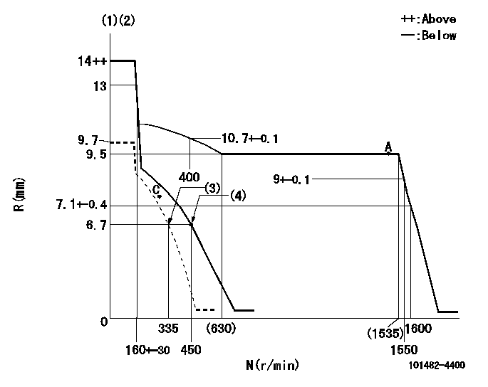
N:Pump speed
R:Rack position (mm)
(1)Target notch: K
(2)Tolerance for racks not indicated: +-0.05mm.
(3)Set idle sub-spring
(4)Main spring setting
----------
K=10
----------
----------
K=10
----------
Speed control lever angle
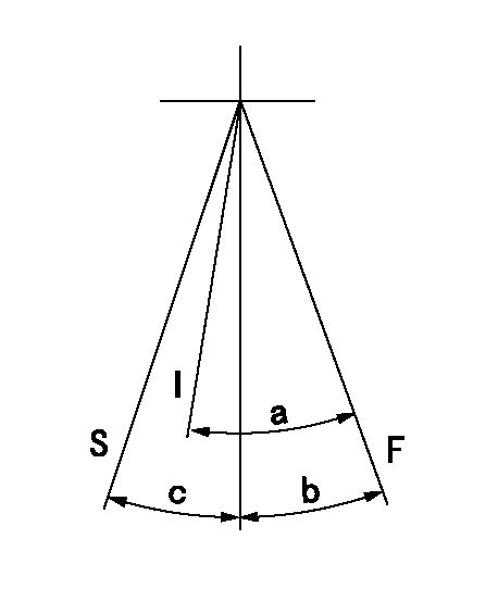
F:Full speed
I:Idle
S:Stop
----------
----------
a=(27deg)+-5deg b=(16deg)+-5deg c=32deg+-3deg
----------
----------
a=(27deg)+-5deg b=(16deg)+-5deg c=32deg+-3deg
Stop lever angle
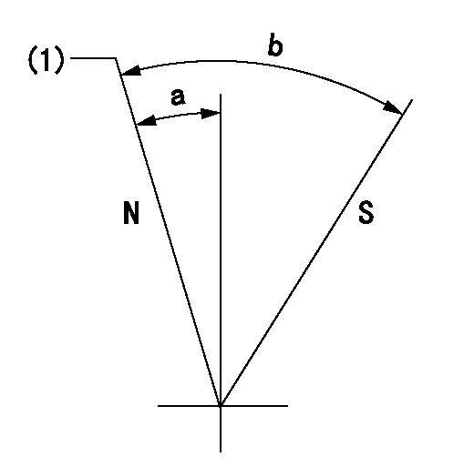
N:Pump normal
S:Stop the pump.
(1)Normal
----------
----------
a=2.5deg+-5deg b=53deg+-5deg
----------
----------
a=2.5deg+-5deg b=53deg+-5deg
Timing setting
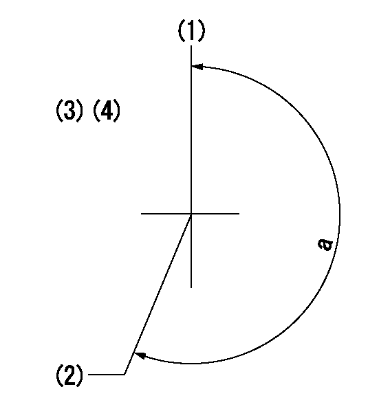
(1)Pump vertical direction
(2)Position of gear mark 'V' at No 1 cylinder's beginning of injection
(3)B.T.D.C.: aa
(4)-
----------
aa=17deg
----------
a=(200deg)
----------
aa=17deg
----------
a=(200deg)
Information:
Vertical Tachometer Drive
Removal
Fig. 1-Vertical Tachometer DriveRemove cap (1, Fig. 1). Lift gasket (2) out of adapter (3).Turn adapter counterclockwise to remove it. Remove aluminum washer (4). Lift pinion (5) out of flywheel housing (6).Repair
Inspect parts for damage. Replace damaged parts.Installation
Coat pinion with engine oil. Put pinion in flywheel housing so that end of pinion rests on machined pad (7) in flywheel housing. Make sure gear teeth on pinion engage teeth on drive gear. IMPORTANT: Adapter can be installed easily only if gears are in mesh.Put aluminum washer over bottom of adapter. Install adapter in flywheel housing. Tighten adapter securely.Flywheel
Removal
If engine is equipped with a clutch, remove the clutch (Group 4052).
Fig. 2-Flywheel Cap ScrewRemove two cap screws (1, Fig. 2) that hold flywheel on crankshaft. Install two pilot studs through flywheel into crankshaft. Tighten pilot studs securely.
Flywheel weighs 50 to 85 lb. (23 to 39 kg). Plan proper handling procedures to avoid injury.
Remove remaining cap screws (2) that hold flywheel on crankshaft.Install two of the cap screws removed in threaded holes in flywheel. Tighten cap screws evenly to push flywheel off crankshaft.Repair
If engine is equipped with a clutch, inspect clutch contact face on flywheel for scoring, overheating, and cracking.
Fig. 3-Flywheel ThicknessClutch contact face can be resurfaced if there is heat checking. Minimum thickness of flywheel at clutch contact face is: IMPORTANT: If heat checks or cracks can be seen after resurfacing flywheel to minimum thickness, install a new flywheel.Inspect ring gear for worn or broken teeth. If damaged, install a new one (Group 0433).Installation
Install two guide studs in crankshaft rear flange. Tighten guide studs securely.
Flywheel weighs 50 to 85 lb. (23 to 39 kg). Plan proper handling procedure to avoid injury.
Move flywheel into position on guide studs. Push flywheel against crankshaft. IMPORTANT: Install new cap screws each time flywheel is removed.
Fig. 4-Flywheel Cap ScrewInstall cap screws and washers. Tighten cap screws evenly to secure flywheel to crankshaft.Remove guide studs from crankshaft. Install remaining cap screws. Tighten cap screws to 120 lb-ft (163 N m).Install clutch, if used (Group 4052).Flywheel Ring Gear
Removal
Remove flywheel (Group 0433).
Fig. 5-Remove Ring GearSelect a hardwood block (1, Fig. 5) that is slightly smaller than the inside diameter of the ring gear (2). Lay the flywheel, crankshaft side down, on the hardwood block.Using a drift and hammer (3), drive the ring gear off the flywheel. Move drift and hammer around ring gear often to prevent cocking the gear on the flywheel.Installation
Oil fumes or oil can ignite above 380°F (193°C). Use a thermometer and do not exceed 360°F (182°C). Do not allow a flame or heating element to be in direct contact with the oil. Heat the oil in a well-ventilated area. Plan a safe handling procedure to avoid burns.
Fig. 6-ChamferHeat new ring gear evenly in oil (to 360°F [182°C] maximum) or in oven (to 450°F [232°C] maximum) and install hot, with ring gear tooth chamfer (Fig. 6) toward engine side of flywheel. Drive ring gear onto flywheel evenly until it bottoms all the way around on
Removal
Fig. 1-Vertical Tachometer DriveRemove cap (1, Fig. 1). Lift gasket (2) out of adapter (3).Turn adapter counterclockwise to remove it. Remove aluminum washer (4). Lift pinion (5) out of flywheel housing (6).Repair
Inspect parts for damage. Replace damaged parts.Installation
Coat pinion with engine oil. Put pinion in flywheel housing so that end of pinion rests on machined pad (7) in flywheel housing. Make sure gear teeth on pinion engage teeth on drive gear. IMPORTANT: Adapter can be installed easily only if gears are in mesh.Put aluminum washer over bottom of adapter. Install adapter in flywheel housing. Tighten adapter securely.Flywheel
Removal
If engine is equipped with a clutch, remove the clutch (Group 4052).
Fig. 2-Flywheel Cap ScrewRemove two cap screws (1, Fig. 2) that hold flywheel on crankshaft. Install two pilot studs through flywheel into crankshaft. Tighten pilot studs securely.
Flywheel weighs 50 to 85 lb. (23 to 39 kg). Plan proper handling procedures to avoid injury.
Remove remaining cap screws (2) that hold flywheel on crankshaft.Install two of the cap screws removed in threaded holes in flywheel. Tighten cap screws evenly to push flywheel off crankshaft.Repair
If engine is equipped with a clutch, inspect clutch contact face on flywheel for scoring, overheating, and cracking.
Fig. 3-Flywheel ThicknessClutch contact face can be resurfaced if there is heat checking. Minimum thickness of flywheel at clutch contact face is: IMPORTANT: If heat checks or cracks can be seen after resurfacing flywheel to minimum thickness, install a new flywheel.Inspect ring gear for worn or broken teeth. If damaged, install a new one (Group 0433).Installation
Install two guide studs in crankshaft rear flange. Tighten guide studs securely.
Flywheel weighs 50 to 85 lb. (23 to 39 kg). Plan proper handling procedure to avoid injury.
Move flywheel into position on guide studs. Push flywheel against crankshaft. IMPORTANT: Install new cap screws each time flywheel is removed.
Fig. 4-Flywheel Cap ScrewInstall cap screws and washers. Tighten cap screws evenly to secure flywheel to crankshaft.Remove guide studs from crankshaft. Install remaining cap screws. Tighten cap screws to 120 lb-ft (163 N m).Install clutch, if used (Group 4052).Flywheel Ring Gear
Removal
Remove flywheel (Group 0433).
Fig. 5-Remove Ring GearSelect a hardwood block (1, Fig. 5) that is slightly smaller than the inside diameter of the ring gear (2). Lay the flywheel, crankshaft side down, on the hardwood block.Using a drift and hammer (3), drive the ring gear off the flywheel. Move drift and hammer around ring gear often to prevent cocking the gear on the flywheel.Installation
Oil fumes or oil can ignite above 380°F (193°C). Use a thermometer and do not exceed 360°F (182°C). Do not allow a flame or heating element to be in direct contact with the oil. Heat the oil in a well-ventilated area. Plan a safe handling procedure to avoid burns.
Fig. 6-ChamferHeat new ring gear evenly in oil (to 360°F [182°C] maximum) or in oven (to 450°F [232°C] maximum) and install hot, with ring gear tooth chamfer (Fig. 6) toward engine side of flywheel. Drive ring gear onto flywheel evenly until it bottoms all the way around on
Have questions with 101482-4400?
Group cross 101482-4400 ZEXEL
Isuzu
101482-4400
9 400 614 245
8970155790
INJECTION-PUMP ASSEMBLY
4JB1
4JB1