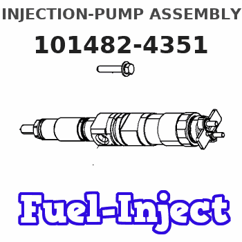
Information injection-pump assembly
BOSCH
9 400 611 687
9400611687
ZEXEL
101482-4351
1014824351
ISUZU
8943811481
8943811481
Rating:
Service parts 101482-4351 INJECTION-PUMP ASSEMBLY:
1.
_
5.
AUTOM. ADVANCE MECHANIS
6.
COUPLING PLATE
8.
_
9.
_
11.
Nozzle and Holder
8-94122-262-5
12.
Open Pre:MPa(Kqf/cm2)
18.1{185}
15.
NOZZLE SET
Cross reference number
BOSCH
9 400 611 687
9400611687
ZEXEL
101482-4351
1014824351
ISUZU
8943811481
8943811481
Zexel num
Bosch num
Firm num
Name
101482-4351
9 400 611 687
8943811481 ISUZU
INJECTION-PUMP ASSEMBLY
4JB1 K 14BC INJECTION PUMP ASSY PE4A,5A, PE
4JB1 K 14BC INJECTION PUMP ASSY PE4A,5A, PE
Calibration Data:
Adjustment conditions
Test oil
1404 Test oil ISO4113 or {SAEJ967d}
1404 Test oil ISO4113 or {SAEJ967d}
Test oil temperature
degC
40
40
45
Nozzle and nozzle holder
105780-8140
Bosch type code
EF8511/9A
Nozzle
105780-0000
Bosch type code
DN12SD12T
Nozzle holder
105780-2080
Bosch type code
EF8511/9
Opening pressure
MPa
17.2
Opening pressure
kgf/cm2
175
Injection pipe
Outer diameter - inner diameter - length (mm) mm 6-2-600
Outer diameter - inner diameter - length (mm) mm 6-2-600
Tester oil delivery pressure
kPa
157
157
157
Tester oil delivery pressure
kgf/cm2
1.6
1.6
1.6
Direction of rotation (viewed from drive side)
Left L
Left L
Injection timing adjustment
Direction of rotation (viewed from drive side)
Left L
Left L
Injection order
1-3-4-2
Pre-stroke
mm
3.3
3.25
3.35
Beginning of injection position
Drive side NO.1
Drive side NO.1
Difference between angles 1
Cal 1-3 deg. 90 89.5 90.5
Cal 1-3 deg. 90 89.5 90.5
Difference between angles 2
Cal 1-4 deg. 180 179.5 180.5
Cal 1-4 deg. 180 179.5 180.5
Difference between angles 3
Cyl.1-2 deg. 270 269.5 270.5
Cyl.1-2 deg. 270 269.5 270.5
Injection quantity adjustment
Adjusting point
A
Rack position
9.8
Pump speed
r/min
1500
1500
1500
Average injection quantity
mm3/st.
49.7
48.7
50.7
Max. variation between cylinders
%
0
-2.5
2.5
Basic
*
Fixing the lever
*
Injection quantity adjustment_02
Adjusting point
B
Rack position
7.6+-0.5
Pump speed
r/min
300
300
300
Average injection quantity
mm3/st.
8
6
10
Max. variation between cylinders
%
0
-15
15
Fixing the rack
*
Test data Ex:
Governor adjustment
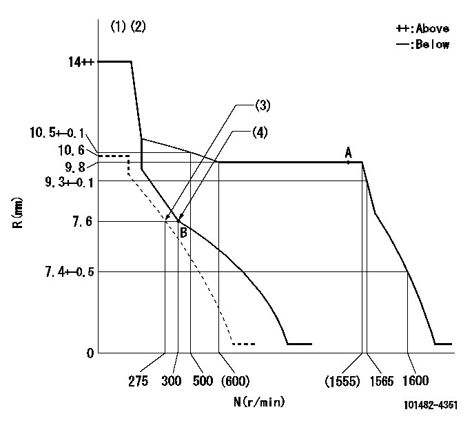
N:Pump speed
R:Rack position (mm)
(1)Target notch: K
(2)Tolerance for racks not indicated: +-0.05mm.
(3)Set idle sub-spring
(4)Main spring setting
----------
K=7
----------
----------
K=7
----------
Speed control lever angle
F:Full speed
I:Idle
S:Stop
----------
----------
a=29deg+-5deg b=11deg+-5deg c=32deg+-3deg
----------
----------
a=29deg+-5deg b=11deg+-5deg c=32deg+-3deg
Stop lever angle
N:Pump normal
S:Stop the pump.
----------
----------
a=0deg+-5deg b=53deg+-5deg
----------
----------
a=0deg+-5deg b=53deg+-5deg
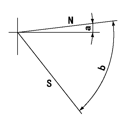
Timing setting
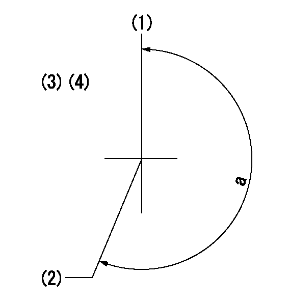
(1)Pump vertical direction
(2)Position of gear mark 'V' at No 1 cylinder's beginning of injection
(3)B.T.D.C.: aa
(4)-
----------
aa=20deg
----------
a=(200deg)
----------
aa=20deg
----------
a=(200deg)
Information:
General Information
Fig. 1-Engine Balancer ShaftsTwo types of balancer shafts are used (Fig. 1). They are mounted in the lower half of the cylinder block and each rotates in three pressure-lubricated replaceable bushings.The balancer shafts rotate in opposite directions to reduce engine vibration. Thrust of the balancer shafts is absorbed by thrust plates fastened to the front of the cylinder block.Removal
Remove fan belts, alternator, and fan.Remove oil pan.Disconnect oil cooler lines.Use a pulley puller to remove the crankshaft pulley.Remove the timing gear cover.Remove weights (2, Fig. 1), from the balancer shafts, if equipped.Remove oil pump gear and lower idler gear.Remove balancer shafts and identify as left and right.Remove balancer shaft gears (4, Fig. 1) by pressing them off.Remove balancer shaft thrust plates (3, Fig. 1).Repair
Fig. 2-Balancer Shaft Journals and Bushings MeasurementCheck oil clearance between balancer shaft journals (2, Fig. 2) and bushings (1). Maximum allowable clearance is 0.0058 in. (0.147 mm). If clearance is greater than this replace the bushings. If oil clearance is still too large, the balancer shaft must be replaced.
Fig. 3-Bushing RemovalThe first two bushings can be replaced using JD-249 Tool, Fig. 3.To remove the third bushing the flywheel housing must be removed, see Group 0433. IMPORTANT: Be sure that hole in each bushing lines up with upper oil lead hole in cylinder block.Press all bushings in from the front of the engine until flush with bushing bore chamfer in block using JD249 Tool.Inspect balancer shaft gears for worn, cracked or broken teeth.Installing Drive Gear
It may be necessary to place thrust plate on the shaft before installing the gear on the shaft depending on the type of thrust plate used.
Fig. 4-Replacing Balancer Shaft GearPosition balancer shaft drive gear on front of balancer shaft so slot in gear lines up with special key, and timing mark on front of gear faces away from balancer shaft. Press on gear using JD-247 Holding Tool to support shaft as shown in Fig. 4. Press gear on shaft with thrust plate in position. Clearance between thrust plate and gear should be 0.002 to 0.010 in. (0.05 to 0.25 mm).Installation
Apply a light film of oil to balancer journals and bushings.Secure thrust plates to front plate with hardware and tighten with 35 lb-ft (47 Nm) (5 kg-m).
Fig. 5-Timing Balancer ShaftInstall balancer shafts in their respective bores. Time balancer shafts as shown in Fig. 5 using JD254 Timing Tool.With a dial indicator check balancer shaft for end play of no more than 0.010 in. (0.25 mm) or no less than 0.002 in. (0.05 mm).
Fig. 6-Installing Balancer Shaft WeightsInstall balancer shaft weights, if used, being sure weights are installed on the machine surfaces of the shaft. Run the balancer shaft bolts through the weights and then through the shafts as shown in Fig. 6. Tighten special nuts to 43 lb-ft (58 N m) (6 kg-m).Replace oil pump gear and lower idler gear if necessary.
Fig. 7-Installing Timing Gear CoverInstall timing gear cover and crankshaft pulley (Fig. 7).Install engine oil cooler coolant hose.Install fan, alternator and fan
Have questions with 101482-4351?
Group cross 101482-4351 ZEXEL
Isuzu
101482-4351
9 400 611 687
8943811481
INJECTION-PUMP ASSEMBLY
4JB1
4JB1