Information injection-pump assembly
ZEXEL
101482-4340
1014824340
ISUZU
8943808530
8943808530
Rating:
Cross reference number
ZEXEL
101482-4340
1014824340
ISUZU
8943808530
8943808530
Zexel num
Bosch num
Firm num
Name
Calibration Data:
Adjustment conditions
Test oil
1404 Test oil ISO4113 or {SAEJ967d}
1404 Test oil ISO4113 or {SAEJ967d}
Test oil temperature
degC
40
40
45
Nozzle and nozzle holder
105780-8140
Bosch type code
EF8511/9A
Nozzle
105780-0000
Bosch type code
DN12SD12T
Nozzle holder
105780-2080
Bosch type code
EF8511/9
Opening pressure
MPa
17.2
Opening pressure
kgf/cm2
175
Injection pipe
Outer diameter - inner diameter - length (mm) mm 6-2-600
Outer diameter - inner diameter - length (mm) mm 6-2-600
Overflow valve
131424-0820
Overflow valve opening pressure
kPa
127
107
147
Overflow valve opening pressure
kgf/cm2
1.3
1.1
1.5
Tester oil delivery pressure
kPa
157
157
157
Tester oil delivery pressure
kgf/cm2
1.6
1.6
1.6
Direction of rotation (viewed from drive side)
Left L
Left L
Injection timing adjustment
Direction of rotation (viewed from drive side)
Left L
Left L
Injection order
1-3-4-2
Pre-stroke
mm
3.3
3.25
3.35
Beginning of injection position
Drive side NO.1
Drive side NO.1
Difference between angles 1
Cal 1-3 deg. 90 89.5 90.5
Cal 1-3 deg. 90 89.5 90.5
Difference between angles 2
Cal 1-4 deg. 180 179.5 180.5
Cal 1-4 deg. 180 179.5 180.5
Difference between angles 3
Cyl.1-2 deg. 270 269.5 270.5
Cyl.1-2 deg. 270 269.5 270.5
Injection quantity adjustment
Adjusting point
A
Rack position
9.6
Pump speed
r/min
900
900
900
Average injection quantity
mm3/st.
39.3
38.3
40.3
Max. variation between cylinders
%
0
-2.5
2.5
Basic
*
Fixing the rack
*
Injection quantity adjustment_02
Adjusting point
B
Rack position
10.1
Pump speed
r/min
875
875
875
Average injection quantity
mm3/st.
45.2
43.2
47.2
Fixing the lever
*
Injection quantity adjustment_03
Adjusting point
D
Rack position
7.8+-0.5
Pump speed
r/min
300
300
300
Average injection quantity
mm3/st.
8.6
6.6
10.6
Max. variation between cylinders
%
0
-15
15
Fixing the rack
*
Test data Ex:
Governor adjustment
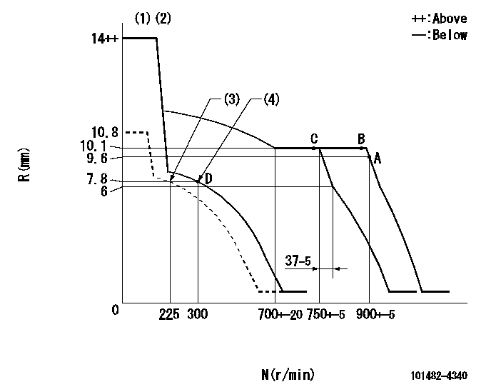
N:Pump speed
R:Rack position (mm)
(1)Target notch: K
(2)The torque control spring does not operate.
(3)Set idle sub-spring
(4)Main spring setting
----------
K=8
----------
----------
K=8
----------
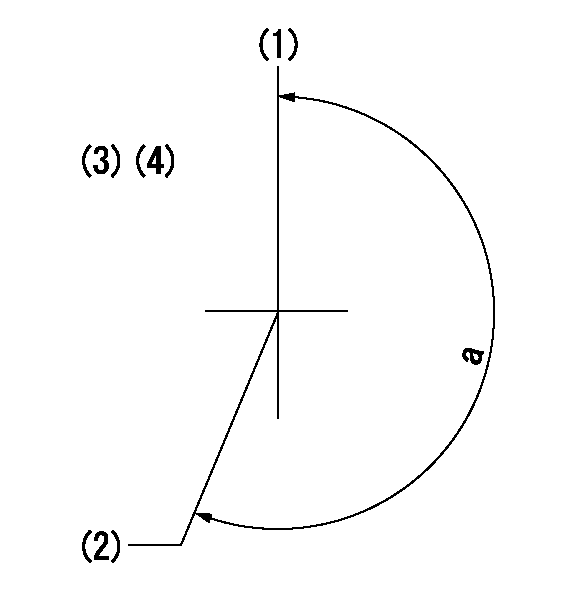
Speed control lever angle
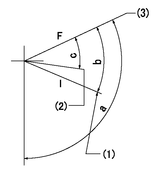
F:Full speed
I:Idle
(1)Stopper bolt setting
(2)Set the pump speed at aa
(3)Set the pump speed at bb (at delivery)
----------
aa=750r/min bb=900r/min
----------
a=93deg+-5deg b=19deg+-5deg c=5deg+-5deg
----------
aa=750r/min bb=900r/min
----------
a=93deg+-5deg b=19deg+-5deg c=5deg+-5deg
Stop lever angle
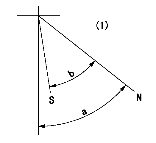
N:Pump normal
S:Stop the pump.
(1)No return spring
----------
----------
a=66.5deg+-5deg b=53deg+-5deg
----------
----------
a=66.5deg+-5deg b=53deg+-5deg
Timing setting
(1)Pump vertical direction
(2)Position of gear mark 'V' at No 1 cylinder's beginning of injection
(3)B.T.D.C.: aa
(4)-
----------
aa=17deg
----------
a=(200deg)
----------
aa=17deg
----------
a=(200deg)
Information:
Cylinder Liner
Use same piston which was removed from cylinder liner being checked.Use the following procedure to check a liner:
Fig. 6-Piston to Liner Clearance1. Put piston in liner with piston "front" and liner "front" aligned. Move piston down until bottom edge of piston skirt is 1.00 in. (25.4 mm) (1, Fig. 6) above bottom of liner.Use a feeler gauge to measure distance (2) between piston skirt and liner 90° to piston pin bore. Record the measured distance (2).Piston to cylinder liner clearance for new parts is: 2. Turn piston 90° in liner. Use a feeler gauge to measure distance between piston skirt and liner 90° to piston pin bore. Record the measured distance.The difference between the distance measured in Step 1 and the distance in Step 2 is the distance the liner is out of round at the bottom of the liner.
Fig. 7-Piston to Liner Clearance3. Pull piston out of liner. Put piston in liner up-side down with piston "front" and liner "front" aligned. Move piston so bottom edge of piston skirt is 1.00 in. (25.4 mm) (1, Fig. 7) below top of liner.Use a feeler gauge to measure distance (2) between piston skirt and liner at 90° to piston pin bore. Record the measured distance (2).4. Turn piston 90° in liner. Use a feeler gauge to measure distance between piston skirt and liner 90° to piston pin bore. Record the measured distance.The difference between the distance measured in Step 3 and the distance measured in Step 4 is the distance the liner is out of round at the top of the liner.If liner is out of round more than 0.002 in. (0.05 mm), at top or bottom, install a new one.5. Find difference between distance measured in Step 1 and distance measured in Step 3. This is the distance the liner is tapered.If liner is tapered more than 0.002 in. (0.05 mm), install a new one.Use a wire brush to carefully remove all rust and scale from the outside of the cylinder liners. Make certain there are no nicks or burrs in the areas where the packings will seat.After removing the rust and scale from the cylinder liners wash thoroughly with solvent and dry them.
Fig. 8-D17004BR Cylinder BrushUse D17004BR Cylinder Brush (Fig. 8) to deglaze each cylinder liner. Match the existing cross hatch pattern when deglazing.Refer to "Basic Engine" in FOS Manual-ENGINES for additional information on deglazing cylinder liners.Immediately after deglazing, clean cylinder liner bore with waterless hand cleaner or soap. Rinse cylinder liner bores with clean water until rinse water is clear. Dry liners with clean towels. Wipe bore with clean engine oil. IMPORTANT: Solvents will not remove honing residue.Recheck liner-to-piston skirt clearance. See Group 0403 for piston repair.Piston Cooling Orifices
Inspect for damage or clogging.
Fig. 9-Piston Cooling OrificeIf a piston cooling orifice (2, Fig. 9) is clogged, use a soft wire (1) to push material out of hole.If an orifice is damaged install a new one.Installation
Fig. 10-Piston Cooling OrificesInstall piston cooling orifices (Fig. 10) and tighten to