Information injection-pump assembly
BOSCH
9 400 614 238
9400614238
ZEXEL
101482-4321
1014824321
ISUZU
8943627541
8943627541
Rating:
Service parts 101482-4321 INJECTION-PUMP ASSEMBLY:
1.
_
5.
AUTOM. ADVANCE MECHANIS
6.
COUPLING PLATE
8.
_
9.
_
11.
Nozzle and Holder
8-94122-262-5
12.
Open Pre:MPa(Kqf/cm2)
18.1{185}
15.
NOZZLE SET
Cross reference number
BOSCH
9 400 614 238
9400614238
ZEXEL
101482-4321
1014824321
ISUZU
8943627541
8943627541
Zexel num
Bosch num
Firm num
Name
Calibration Data:
Adjustment conditions
Test oil
1404 Test oil ISO4113 or {SAEJ967d}
1404 Test oil ISO4113 or {SAEJ967d}
Test oil temperature
degC
40
40
45
Nozzle and nozzle holder
105780-8140
Bosch type code
EF8511/9A
Nozzle
105780-0000
Bosch type code
DN12SD12T
Nozzle holder
105780-2080
Bosch type code
EF8511/9
Opening pressure
MPa
17.2
Opening pressure
kgf/cm2
175
Injection pipe
Outer diameter - inner diameter - length (mm) mm 6-2-600
Outer diameter - inner diameter - length (mm) mm 6-2-600
Tester oil delivery pressure
kPa
157
157
157
Tester oil delivery pressure
kgf/cm2
1.6
1.6
1.6
Direction of rotation (viewed from drive side)
Left L
Left L
Injection timing adjustment
Direction of rotation (viewed from drive side)
Left L
Left L
Injection order
1-3-4-2
Pre-stroke
mm
3.3
3.25
3.35
Beginning of injection position
Drive side NO.1
Drive side NO.1
Difference between angles 1
Cal 1-3 deg. 90 89.5 90.5
Cal 1-3 deg. 90 89.5 90.5
Difference between angles 2
Cal 1-4 deg. 180 179.5 180.5
Cal 1-4 deg. 180 179.5 180.5
Difference between angles 3
Cyl.1-2 deg. 270 269.5 270.5
Cyl.1-2 deg. 270 269.5 270.5
Injection quantity adjustment
Adjusting point
A
Rack position
10.7
Pump speed
r/min
1600
1600
1600
Average injection quantity
mm3/st.
59.5
58.5
60.5
Max. variation between cylinders
%
0
-2.5
2.5
Basic
*
Fixing the lever
*
Injection quantity adjustment_02
Adjusting point
B
Rack position
7.8+-0.5
Pump speed
r/min
275
275
275
Average injection quantity
mm3/st.
9.5
7.5
11.5
Max. variation between cylinders
%
0
-15
15
Fixing the rack
*
Test data Ex:
Governor adjustment
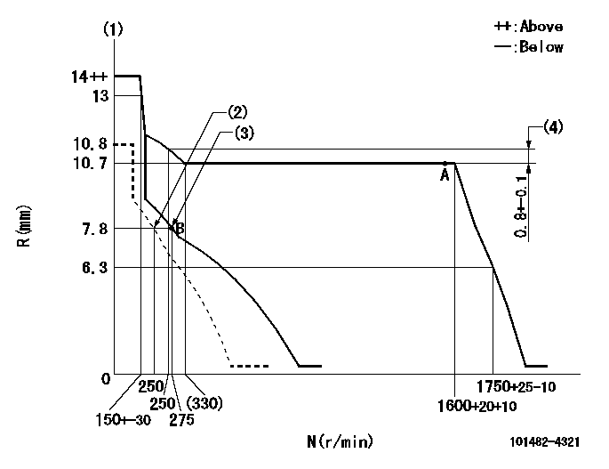
N:Pump speed
R:Rack position (mm)
(1)Target notch: K
(2)Set idle sub-spring
(3)Main spring setting
(4)Rack difference from N = N1
----------
K=11 N1=1600r/min
----------
----------
K=11 N1=1600r/min
----------
Speed control lever angle
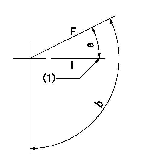
F:Full speed
I:Idle
(1)Stopper bolt setting
----------
----------
a=(31deg)+-5deg b=(121deg)+-5deg
----------
----------
a=(31deg)+-5deg b=(121deg)+-5deg
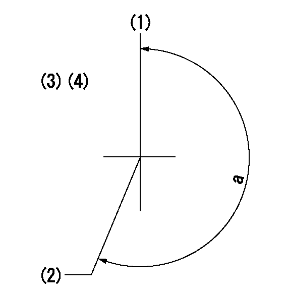
Stop lever angle
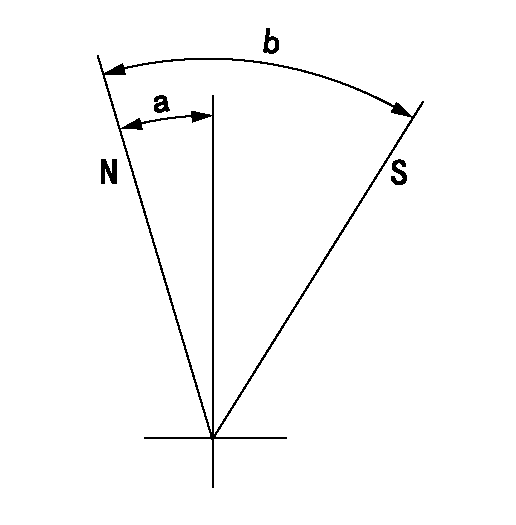
N:Pump normal
S:Stop the pump.
----------
----------
a=2.5deg+-5deg b=53deg+-5deg
----------
----------
a=2.5deg+-5deg b=53deg+-5deg
Timing setting
(1)Pump vertical direction
(2)Position of gear mark 'V' at No 1 cylinder's beginning of injection
(3)-
(4)-
----------
----------
a=(200deg)
----------
----------
a=(200deg)
Information:
Repair
Measure crankshaft main journal to main bearing clearance.
Fig. 5-Main Bearing ClearanceMain bearing journal O.D. (new) (1, Fig. 5) ... 3.123 to 3.124 inch(79.32 to 79.35 mm)Assembled Main bearing I.D. (new) (2) ... 3.126 to 3.128 inch(79.39 to 79.45 mm)Main bearing clearance (new) (3) ... 0.0016 to 0.0046 inch(0.041 to 0.117 mm)Main bearing clearance (maximum) ... 0.006 inch(0.15 mm)Main bearing bore I.D. (4) ... 3.325 to 3.326 inch(84.46 to 84.48 mm)Measure crankshaft main journal taper and roundness.
Fig. 6-Main Bearing MeasurementJournal taper (maximum) (1, Fig. 6) ... 0.001 inch per 1.00 inch(0.03 mm per 25.4 mm)Journal out-of-round (maximum) (2, Fig. 6) ... 0.003 inch(0.08 mm)If wear is even, but out of specifications, dress crankshaft main journals and select proper undersize bearing inserts.If journals are out-of-round or tapered, grind crankshaft and select proper undersize bearing inserts.If crankshaft end play is excessive, replace worn thrust bearings or grind crankshaft thrust surfaces and select proper oversize thrust bearing.Installation
Fig. 7-Main Bearing Insert InstallationPosition bearing inserts in cylinder block and main bearing caps with the tang on the insert engaged in the slot in the cylinder block and main bearing caps (Fig. 7).Apply a coat of clean engine oil to the bearing surface of the inserts.Position crankshaft in cylinder block. Tangs on main bearing halves in main bearing caps must be positioned to the same side of the crankshaft as the tangs on main bearing halves in cylinder block.
Fig. 8-Main Bearing Cap PositionsInstall main bearing caps with numbers (1, Fig. 8) corresponding to numbers in oil pan rail (2). If there is no arrow (3) machined on main bearing cap, install cap with number to same side as numbers in oil pan rail. If there is an arrow machined on main bearing cap, arrow must point toward camshaft side.Dip main bearing cap screws in clean engine oil and position them in the main bearing caps. IMPORTANT: Do not use pneumatic wrench to install main bearing cap screws.Before tightening cap screws on main bearing caps, align upper and lower thrust flanges on main thrust bearings. Using a soft-face hammer, tap crankshaft to the rear and then to the front to line up thrust bearing flanges.Rotate crankshaft by hand. Crankshaft should rotate with little effort.
Fig. 9-Main Bearing Cap ScrewTighten main bearing cap screws (Fig. 9)Main bearing cap screw torque ... 85 lb-ft(115 N m) (12 kg-m)Turn crankshaft by hand. If it does not turn easily, disassemble parts and determine the cause.Pull piston and connecting rods into position against the crankshaft.Install connecting rod caps (Group 0403).Install engine front plate (Group 0404).Install camshaft (Group 0402).Install timing gear train (Group 0402).Install timing gear cover (Group 0402).Install vibration damper (Group 0401).Install fan belt and alternator belt (Group 0429).Install flywheel housing (Group 0433).Install flywheel (Group 0433).Install oil pan (Group 0407).Install pushrods and rocker arm assembly (Group 0402).Install rocker arm cover (Group 0402).Install fuel transfer pump (Group 0421).Crankshaft Gear
Removal
Remove crankshaft from engine (Group 0401).
Fig. 10-Crankshaft Gear RemovalUse knife-edge puller (1, Fig. 10) to remove crankshaft gear (2) from