Information injection-pump assembly
ZEXEL
101482-4222
1014824222
ISUZU
8944627552
8944627552

Rating:
Cross reference number
ZEXEL
101482-4222
1014824222
ISUZU
8944627552
8944627552
Zexel num
Bosch num
Firm num
Name
Calibration Data:
Adjustment conditions
Test oil
1404 Test oil ISO4113 or {SAEJ967d}
1404 Test oil ISO4113 or {SAEJ967d}
Test oil temperature
degC
40
40
45
Nozzle and nozzle holder
105780-8140
Bosch type code
EF8511/9A
Nozzle
105780-0000
Bosch type code
DN12SD12T
Nozzle holder
105780-2080
Bosch type code
EF8511/9
Opening pressure
MPa
17.2
Opening pressure
kgf/cm2
175
Injection pipe
Outer diameter - inner diameter - length (mm) mm 6-2-600
Outer diameter - inner diameter - length (mm) mm 6-2-600
Tester oil delivery pressure
kPa
157
157
157
Tester oil delivery pressure
kgf/cm2
1.6
1.6
1.6
Direction of rotation (viewed from drive side)
Left L
Left L
Injection timing adjustment
Direction of rotation (viewed from drive side)
Left L
Left L
Injection order
1-3-4-2
Pre-stroke
mm
3.3
3.25
3.35
Beginning of injection position
Drive side NO.1
Drive side NO.1
Difference between angles 1
Cal 1-3 deg. 90 89.5 90.5
Cal 1-3 deg. 90 89.5 90.5
Difference between angles 2
Cal 1-4 deg. 180 179.5 180.5
Cal 1-4 deg. 180 179.5 180.5
Difference between angles 3
Cyl.1-2 deg. 270 269.5 270.5
Cyl.1-2 deg. 270 269.5 270.5
Injection quantity adjustment
Adjusting point
A
Rack position
9.5
Pump speed
r/min
1500
1500
1500
Average injection quantity
mm3/st.
48
47
49
Max. variation between cylinders
%
0
-2.5
2.5
Basic
*
Fixing the lever
*
Injection quantity adjustment_02
Adjusting point
C
Rack position
8.8+-0.5
Pump speed
r/min
300
300
300
Average injection quantity
mm3/st.
13
11
15
Max. variation between cylinders
%
0
-15
15
Fixing the rack
*
Remarks
Adjust only variation between cylinders; adjust governor according to governor specifications.
Adjust only variation between cylinders; adjust governor according to governor specifications.
Test data Ex:
Governor adjustment
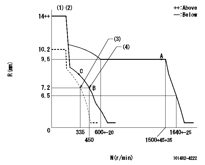
N:Pump speed
R:Rack position (mm)
(1)Target notch: K
(2)The torque control spring does not operate.
(3)Set idle sub-spring
(4)Main spring setting
----------
K=16
----------
----------
K=16
----------
Speed control lever angle
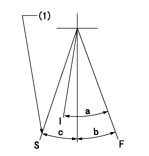
F:Full speed
I:Idle
S:Stop
(1)Set point B
----------
----------
a=(26deg)+-5deg b=(22deg)+-5deg c=32deg+-3deg
----------
----------
a=(26deg)+-5deg b=(22deg)+-5deg c=32deg+-3deg
Stop lever angle
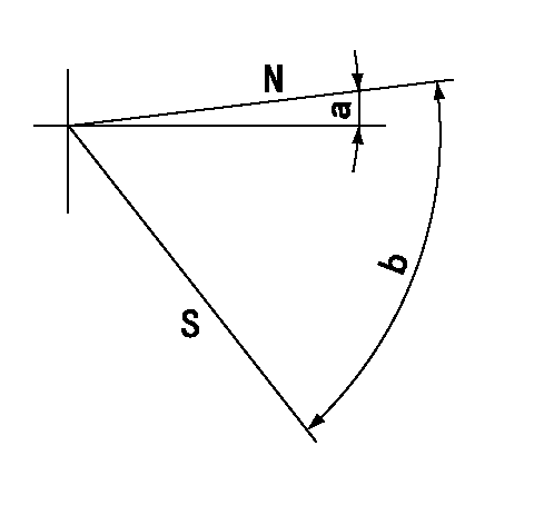
N:Pump normal
S:Stop the pump.
----------
----------
a=0deg+-5deg b=53deg+-5deg
----------
----------
a=0deg+-5deg b=53deg+-5deg
Timing setting
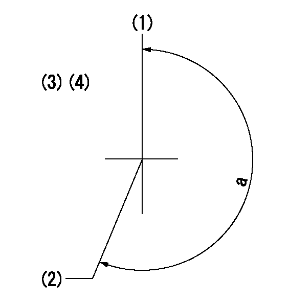
(1)Pump vertical direction
(2)Position of gear mark 'V' at No 1 cylinder's beginning of injection
(3)B.T.D.C.: aa
(4)-
----------
aa=20deg
----------
a=(200deg)
----------
aa=20deg
----------
a=(200deg)
Information:
ACTION REQUIRED
If your engine is experiencing a lack of power and/or black smoke emissions, complete the following action:
- Replace the six fuel injectors at the time of repair
Refer to KENR8106, Disassembly and Assembly, for removal/install procedure of the fuel injector groups.
It is recommended that REBE8794 be performed at the same time as REBE8786.
Refer to REHS7468, Special Instruction, "Procedure to Replace Fuel Filters in Certain 320D and 323D Excavators and Mobile Hydraulic Power Units", for the Rework Procedure.
SERVICE CLAIM ALLOWANCES
Product smu/age whichever comes first Caterpillar Dealer Suggested Customer Suggested
Parts % Labor Hrs% Parts % Labor Hrs% Parts % Labor Hrs%
*******Group 1*******
0-3500 hrs,
0-24 mo 100.0% 100.0% 0.0% 0.0% 0.0% 0.0%
3501-6000 hrs,
25-48 mo 33.0% 33.0% 25.0% 33.0% 25.0% 34.0%
This is a 4.0-hour job for Group 1
Product smu/age whichever comes first Caterpillar Dealer Suggested Customer Suggested
Parts % Labor Hrs% Parts % Labor Hrs% Parts % Labor Hrs%
*******Group 2*******
0-3500 hrs,
0-24 mo 100.0% 100.0% 0.0% 0.0% 0.0% 0.0%
3501-6000 hrs,
25-48 mo 33.0% 33.0% 25.0% 33.0% 25.0% 34.0%
This is a 4.0-hour job for Group 2
PARTS DISPOSITION
Handle the parts in accordance with your Warranty Bulletin on warranty parts handling.