Information injection-pump assembly
BOSCH
9 400 614 206
9400614206
ZEXEL
101481-9110
1014819110
NISSAN-DIESEL
1671290113
1671290113

Rating:
Service parts 101481-9110 INJECTION-PUMP ASSEMBLY:
1.
_
6.
COUPLING PLATE
7.
COUPLING PLATE
8.
_
9.
_
11.
Nozzle and Holder
16600-T9300
12.
Open Pre:MPa(Kqf/cm2)
21.6{220}

15.
NOZZLE SET
Cross reference number
BOSCH
9 400 614 206
9400614206
ZEXEL
101481-9110
1014819110
NISSAN-DIESEL
1671290113
1671290113
Zexel num
Bosch num
Firm num
Name
101481-9110
9 400 614 206
1671290113 NISSAN-DIESEL
INJECTION-PUMP ASSEMBLY
FD33T K 14BC INJECTION PUMP ASSY PE4A,5A, PE
FD33T K 14BC INJECTION PUMP ASSY PE4A,5A, PE
Calibration Data:
Adjustment conditions
Test oil
1404 Test oil ISO4113 or {SAEJ967d}
1404 Test oil ISO4113 or {SAEJ967d}
Test oil temperature
degC
40
40
45
Nozzle and nozzle holder
105780-8140
Bosch type code
EF8511/9A
Nozzle
105780-0000
Bosch type code
DN12SD12T
Nozzle holder
105780-2080
Bosch type code
EF8511/9
Opening pressure
MPa
17.2
Opening pressure
kgf/cm2
175
Injection pipe
Outer diameter - inner diameter - length (mm) mm 6-2-600
Outer diameter - inner diameter - length (mm) mm 6-2-600
Overflow valve
131424-1520
Overflow valve opening pressure
kPa
157
123
191
Overflow valve opening pressure
kgf/cm2
1.6
1.25
1.95
Tester oil delivery pressure
kPa
157
157
157
Tester oil delivery pressure
kgf/cm2
1.6
1.6
1.6
Direction of rotation (viewed from drive side)
Right R
Right R
Injection timing adjustment
Direction of rotation (viewed from drive side)
Right R
Right R
Injection order
1-3-4-2
Pre-stroke
mm
2.8
2.75
2.85
Beginning of injection position
Drive side NO.1
Drive side NO.1
Difference between angles 1
Cal 1-3 deg. 90 89.5 90.5
Cal 1-3 deg. 90 89.5 90.5
Difference between angles 2
Cal 1-4 deg. 180 179.5 180.5
Cal 1-4 deg. 180 179.5 180.5
Difference between angles 3
Cyl.1-2 deg. 270 269.5 270.5
Cyl.1-2 deg. 270 269.5 270.5
Injection quantity adjustment
Adjusting point
A
Rack position
10.2
Pump speed
r/min
1500
1500
1500
Average injection quantity
mm3/st.
67.4
66.3
68.5
Max. variation between cylinders
%
0
-2.5
2.5
Basic
*
Fixing the lever
*
Injection quantity adjustment_02
Adjusting point
B
Rack position
9.8
Pump speed
r/min
1500
1500
1500
Average injection quantity
mm3/st.
58.2
56.2
60.2
Max. variation between cylinders
%
0
-2.5
2.5
Fixing the lever
*
Injection quantity adjustment_03
Adjusting point
-
Rack position
8+-0.5
Pump speed
r/min
300
300
300
Average injection quantity
mm3/st.
10
8
12
Max. variation between cylinders
%
0
-15
15
Fixing the rack
*
Remarks
Adjust only variation between cylinders; adjust governor according to governor specifications.
Adjust only variation between cylinders; adjust governor according to governor specifications.
Injection quantity adjustment_04
Adjusting point
D
Rack position
-
Pump speed
r/min
100
100
100
Average injection quantity
mm3/st.
81
71
91
Fixing the lever
*
Rack limit
*
Timer adjustment
Pump speed
r/min
1350--
Advance angle
deg.
0
0
0
Remarks
Start
Start
Timer adjustment_02
Pump speed
r/min
1300
Advance angle
deg.
0.5
Timer adjustment_03
Pump speed
r/min
1600
Advance angle
deg.
1.8
1.3
2.3
Timer adjustment_04
Pump speed
r/min
1800
Advance angle
deg.
4
3.5
4.5
Remarks
Finish
Finish
Test data Ex:
Governor adjustment
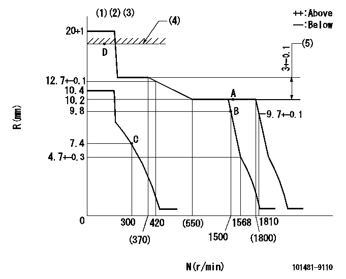
N:Pump speed
R:Rack position (mm)
(1)Target notch: K
(2)Tolerance for racks not indicated: +-0.05mm.
(3)Confirm that the idle sub-spring does not operate at high idle.
(4)RACK LIMIT
(5)Rack difference between N = N1 and N = N2
----------
K=10 N1=1500r/min N2=300r/min
----------
----------
K=10 N1=1500r/min N2=300r/min
----------
Speed control lever angle
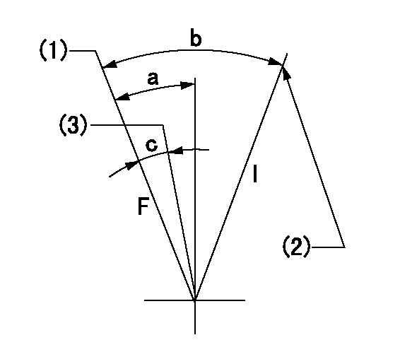
F:Full speed
I:Idle
(1)Set the pump speed at aa. ( At delivery )
(2)Stopper bolt setting
(3)Set the pump speed at bb.
----------
aa=1810r/min bb=1500r/min
----------
a=21deg+-5deg b=32deg+-5deg c=9deg+-5deg
----------
aa=1810r/min bb=1500r/min
----------
a=21deg+-5deg b=32deg+-5deg c=9deg+-5deg
Stop lever angle

N:Pump normal
S:Stop the pump.
----------
----------
a=10.5deg+-5deg b=53deg+-5deg
----------
----------
a=10.5deg+-5deg b=53deg+-5deg
0000001501 GOV FULL LOAD ADJUSTMENT
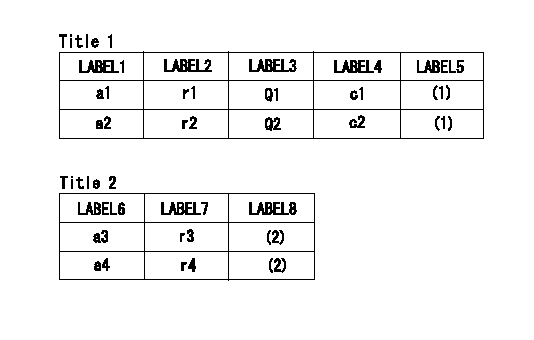
Title1:Full load stopper adjustment
Title2:Governor set speed
LABEL1:Distinguishing
LABEL2:Pump speed (r/min)
LABEL3:Ave. injection quantity (mm3/st)
LABEL4:Max. var. bet. cyl.
LABEL5:Remarks
LABEL6:Distinguishing
LABEL7:Governor set speed (r/min)
LABEL8:Remarks
(1)Adjustment conditions are the same as those for measuring injection quantity.
(2)-
----------
----------
a1=B a2=- r1=1500r/min r2=- Q1=67.4+-1.1mm3/st Q2=- c1=+-2.5% c2=- a3=36 a4=30 r3=1800r/min r4=1500r/min
----------
----------
a1=B a2=- r1=1500r/min r2=- Q1=67.4+-1.1mm3/st Q2=- c1=+-2.5% c2=- a3=36 a4=30 r3=1800r/min r4=1500r/min
Timing setting

(1)Pump vertical direction
(2)Position of gear's standard threaded hole at No 1 cylinder's beginning of injection (position of gear's 'M' mark)
(3)B.T.D.C.: aa
(4)-
----------
aa=14deg
----------
a=(60deg)
----------
aa=14deg
----------
a=(60deg)
Information:
Literature Information
This manual should be stored in the literature storage area.The information contained in this document is the most current information available for coolants, fuels, and lubricants. Refer to the Operation and Maintenance Manual for any special lubrication requirements for your engine.Whenever a question arises regarding the engine, this publication, or the Operation and Maintenance Manual, please consult any Cat dealer for the latest available information.Safety
Refer to the Operation and Maintenance Manual for your engine for all safety information. Read and understand the basic safety precautions listed in the Safety Section. In addition to safety precautions, this section identifies the text and locations of safety signs used on the engine.Read and understand the basic precautions listed in the Safety Section before operating or performing lubrication, maintenance and repair on this engine.Maintenance
Refer to the Operation and Maintenance Manual for your engine to determine all maintenance requirements.Maintenance Intervals
Use the Maintenance Interval Schedule in the Operation and Maintenance Manual for your engine to determine servicing intervals. The actual operating environment of the engine also governs the maintenance interval schedule. Therefore, under extremely severe, dusty, wet or freezing cold operating conditions, more frequent lubrication and maintenance than is specified in the Maintenance Interval Schedule may be necessary.Extended Engine Oil Drains and Warranty
Failures that result from extended oil drain periods are not Caterpillar factory defects and therefore are not covered by Caterpillar's warranty. In addition, failures that result from not using the recommended oil type are not Caterpillar factory defects and therefore are not covered by Caterpillar's warranty.Refer to the applicable Operation and Maintenance Manual for standard oil drain periods and to the Maintenance Section, "Lubricant Specifications" of this publication for engine oil type and viscosity grade recommendations.To reduce the potential risk of failures associated with extended oil drain periods; it is recommended that oil drain intervals only be extended based on oil analysis, and subsequent engine inspections. Oil analysis alone does not provide an indication of the rate of formation of lacquer, varnish and/or carbon on pistons and other engine surfaces. The only accurate way to evaluate specific oil performance in a specific engine and application that utilizes extended oil drain periods is to observe the effects on the engine components. This involves tear-down inspections of engines that have run to their normal overhaul period with extended oil drain intervals. Following this recommendation will help ensure that excessive component wear does not take place in a given application.
Light loads, low hour accumulation, and excessive idling time can contribute to excessive water in the crankcase oil. Corrosive damage, piston deposits and increased oil consumption can also result. If oil analysis is not done or the results are ignored, the potential for corrosive damage and piston deposits increases. Refer to the appropriate Operation and Maintenance Manual for guidance.
Note: Failures that result from extended oil drain periods are not warrantable failures, regardless of use of this recommended procedure. Failures that result from extended engine oil drain periods are considered improper use under the warranty.Aftermarket Products
Have questions with 101481-9110?
Group cross 101481-9110 ZEXEL
Nissan-Diesel
101481-9110
9 400 614 206
1671290113
INJECTION-PUMP ASSEMBLY
FD33T
FD33T