Information injection-pump assembly
ZEXEL
101481-9090
1014819090
NISSAN-DIESEL
16700T9303
16700t9303

Rating:
Cross reference number
ZEXEL
101481-9090
1014819090
NISSAN-DIESEL
16700T9303
16700t9303
Zexel num
Bosch num
Firm num
Name
101481-9090
16700T9303 NISSAN-DIESEL
INJECTION-PUMP ASSEMBLY
FD33T * K
FD33T * K
Calibration Data:
Adjustment conditions
Test oil
1404 Test oil ISO4113 or {SAEJ967d}
1404 Test oil ISO4113 or {SAEJ967d}
Test oil temperature
degC
40
40
45
Nozzle and nozzle holder
105780-8140
Bosch type code
EF8511/9A
Nozzle
105780-0000
Bosch type code
DN12SD12T
Nozzle holder
105780-2080
Bosch type code
EF8511/9
Opening pressure
MPa
17.2
Opening pressure
kgf/cm2
175
Injection pipe
Outer diameter - inner diameter - length (mm) mm 6-2-600
Outer diameter - inner diameter - length (mm) mm 6-2-600
Overflow valve
132424-0620
Overflow valve opening pressure
kPa
157
123
191
Overflow valve opening pressure
kgf/cm2
1.6
1.25
1.95
Tester oil delivery pressure
kPa
157
157
157
Tester oil delivery pressure
kgf/cm2
1.6
1.6
1.6
Direction of rotation (viewed from drive side)
Right R
Right R
Injection timing adjustment
Direction of rotation (viewed from drive side)
Right R
Right R
Injection order
1-3-4-2
Pre-stroke
mm
2.8
2.75
2.85
Beginning of injection position
Drive side NO.1
Drive side NO.1
Difference between angles 1
Cal 1-3 deg. 90 89.5 90.5
Cal 1-3 deg. 90 89.5 90.5
Difference between angles 2
Cal 1-4 deg. 180 179.5 180.5
Cal 1-4 deg. 180 179.5 180.5
Difference between angles 3
Cyl.1-2 deg. 270 269.5 270.5
Cyl.1-2 deg. 270 269.5 270.5
Injection quantity adjustment
Adjusting point
-
Rack position
10.4
Pump speed
r/min
1100
1100
1100
Average injection quantity
mm3/st.
70.4
68.8
72
Max. variation between cylinders
%
0
-2.5
2.5
Basic
*
Fixing the rack
*
Standard for adjustment of the maximum variation between cylinders
*
Injection quantity adjustment_02
Adjusting point
-
Rack position
8.6+-0.5
Pump speed
r/min
300
300
300
Average injection quantity
mm3/st.
10
8
12
Max. variation between cylinders
%
0
-15
15
Fixing the rack
*
Standard for adjustment of the maximum variation between cylinders
*
Remarks
Adjust only variation between cylinders; adjust governor according to governor specifications.
Adjust only variation between cylinders; adjust governor according to governor specifications.
Injection quantity adjustment_03
Adjusting point
A
Rack position
R1(10.4)
Pump speed
r/min
1100
1100
1100
Average injection quantity
mm3/st.
70.4
69.4
71.4
Basic
*
Fixing the lever
*
Boost pressure
kPa
66.7
66.7
Boost pressure
mmHg
500
500
Injection quantity adjustment_04
Adjusting point
B
Rack position
R1(10.4)
Pump speed
r/min
1800
1800
1800
Average injection quantity
mm3/st.
78.2
74.2
82.2
Fixing the lever
*
Boost pressure
kPa
66.7
66.7
Boost pressure
mmHg
500
500
Boost compensator adjustment
Pump speed
r/min
1100
1100
1100
Rack position
R1-1.8
Boost pressure
kPa
16
16
16
Boost pressure
mmHg
120
120
120
Boost compensator adjustment_02
Pump speed
r/min
1100
1100
1100
Rack position
R1-1
Boost pressure
kPa
32
30.7
33.3
Boost pressure
mmHg
240
230
250
Boost compensator adjustment_03
Pump speed
r/min
1100
1100
1100
Rack position
R1(10.4)
Boost pressure
kPa
60
53.3
60
Boost pressure
mmHg
450
400
450
Timer adjustment
Pump speed
r/min
1300+50
Advance angle
deg.
0
0
0
Remarks
Start
Start
Timer adjustment_02
Pump speed
r/min
1600
Advance angle
deg.
1.8
1.3
2.3
Timer adjustment_03
Pump speed
r/min
1800
Advance angle
deg.
4
3.5
4.5
Remarks
Finish
Finish
Test data Ex:
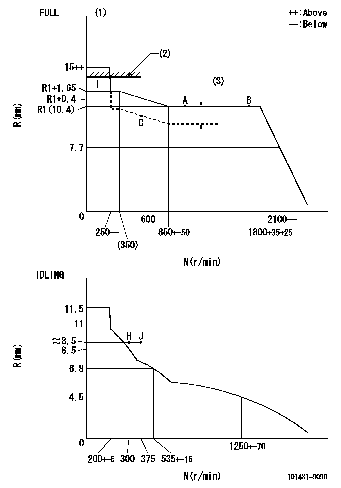
Governor adjustment

N:Pump speed
R:Rack position (mm)
(1)Torque cam stamping: T1
(2)RACK LIMIT: RAL
(3)Boost compensator stroke: BCL
----------
T1=A84 RAL=13.2+0.2mm BCL=1.8+-0.1mm
----------
----------
T1=A84 RAL=13.2+0.2mm BCL=1.8+-0.1mm
----------
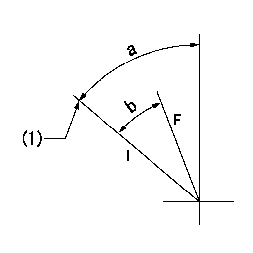
Speed control lever angle

F:Full speed
I:Idle
(1)Stopper bolt set position 'H'
----------
----------
a=60deg+-5deg b=(35deg)+-3deg
----------
----------
a=60deg+-5deg b=(35deg)+-3deg
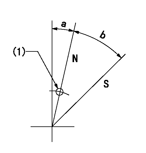
Stop lever angle

N:Pump normal
S:Stop the pump.
(1)Use the pin at R = aa
----------
aa=12mm
----------
a=0deg+-5deg b=40deg+-5deg
----------
aa=12mm
----------
a=0deg+-5deg b=40deg+-5deg
Timing setting

(1)Pump vertical direction
(2)Position of gear's standard threaded hole (position of gear mark 'B') at No 1 cylinder's beginning of injection
(3)B.T.D.C.: aa
(4)-
----------
aa=(14deg)
----------
a=(60deg)
----------
aa=(14deg)
----------
a=(60deg)
Information:
Table 1
Revision Summary of Changes
01 Updated Illustration 1
02 Updated effectivity Introduction
The problem that is identified below does not have a known permanent solution. Until a permanent solution is known, use the solution that is identified below.Problem
Inadequate battery negative bonding to engine block causing incorrect diagnostic codes/tripping in the units that are disconnected from the engine-mounted charging alternator.Solution
Do not operate or work on this product unless you have read and understood the instruction and warnings in the relevant Operation and Maintenance Manuals and relevant service literature. Failure to follow the instructions or heed the warnings could result in injury or death. Proper care is your responsibility.
Illustration 1 g06575359
Generator set isolated DC supply system
(1) Electronic subsystem 1
(2) Electronic subsystem 2
(3) Electronic subsystem 3
(4) Generator set subsystem loads
(5) Engine ECM
(6) Starter
(7) Electronics power buss
(8) Electronics single point ground
(9) 12AWG (4 Sq.mm) bonding jumper (multi strand) wire
(10) Battery disconnect switch
(11) Customer ground connection
(12) Battery
(13) Battery charger
(14) Customer scopeNote: The red color connections in Illustration 1 are to be connected at customer site. Connections should be made after the battery disconnect switch (10).Caterpillar is aware of the problem, and is recommending the following interim solution.Install a 12AWG (4 Sq.mm) bonding jumper (multi strand) wire (9) connecting all electrical sensor grounding points (8) at the power distribution box to the customer ground connection (11). Refer to Illustration 1.Reference: Refer to Special Instruction, REHS4634, "Grounding Design Guide for Electric Power Generation Products".
Have questions with 101481-9090?
Group cross 101481-9090 ZEXEL
Daewoo
Nissan-Diesel
Nissan-Diesel
101481-9090
16700T9303
INJECTION-PUMP ASSEMBLY
FD33T
FD33T