Information injection-pump assembly
ZEXEL
101481-0271
1014810271
ISUZU
8971683121
8971683121
Rating:
Service parts 101481-0271 INJECTION-PUMP ASSEMBLY:
1.
_
6.
COUPLING PLATE
7.
COUPLING PLATE
8.
_
9.
_
11.
Nozzle and Holder
8-97042-322-1
12.
Open Pre:MPa(Kqf/cm2)
13.2{135}
15.
NOZZLE SET
Cross reference number
ZEXEL
101481-0271
1014810271
ISUZU
8971683121
8971683121
Zexel num
Bosch num
Firm num
Name
Calibration Data:
Adjustment conditions
Test oil
1404 Test oil ISO4113 or {SAEJ967d}
1404 Test oil ISO4113 or {SAEJ967d}
Test oil temperature
degC
40
40
45
Nozzle and nozzle holder
105780-8140
Bosch type code
EF8511/9A
Nozzle
105780-0000
Bosch type code
DN12SD12T
Nozzle holder
105780-2080
Bosch type code
EF8511/9
Opening pressure
MPa
17.2
Opening pressure
kgf/cm2
175
Injection pipe
Outer diameter - inner diameter - length (mm) mm 6-2-600
Outer diameter - inner diameter - length (mm) mm 6-2-600
Overflow valve
131424-4920
Overflow valve opening pressure
kPa
127
107
147
Overflow valve opening pressure
kgf/cm2
1.3
1.1
1.5
Tester oil delivery pressure
kPa
157
157
157
Tester oil delivery pressure
kgf/cm2
1.6
1.6
1.6
Direction of rotation (viewed from drive side)
Right R
Right R
Injection timing adjustment
Direction of rotation (viewed from drive side)
Right R
Right R
Injection order
1-3-4-2
Pre-stroke
mm
2.8
2.75
2.85
Rack position
Point A R=A
Point A R=A
Beginning of injection position
Drive side NO.1
Drive side NO.1
Difference between angles 1
Cal 1-3 deg. 90 89.5 90.5
Cal 1-3 deg. 90 89.5 90.5
Difference between angles 2
Cal 1-4 deg. 180 179.5 180.5
Cal 1-4 deg. 180 179.5 180.5
Difference between angles 3
Cyl.1-2 deg. 270 269.5 270.5
Cyl.1-2 deg. 270 269.5 270.5
Injection quantity adjustment
Adjusting point
-
Rack position
11.9
Pump speed
r/min
950
950
950
Average injection quantity
mm3/st.
77
75.4
78.6
Max. variation between cylinders
%
0
-4
4
Basic
*
Fixing the rack
*
Standard for adjustment of the maximum variation between cylinders
*
Injection quantity adjustment_02
Adjusting point
H
Rack position
9.5+-0.5
Pump speed
r/min
400
400
400
Average injection quantity
mm3/st.
13
11.7
14.3
Max. variation between cylinders
%
0
-14
14
Fixing the rack
*
Standard for adjustment of the maximum variation between cylinders
*
Injection quantity adjustment_03
Adjusting point
A
Rack position
R1(11.9)
Pump speed
r/min
950
950
950
Average injection quantity
mm3/st.
77
76
78
Basic
*
Fixing the lever
*
Boost pressure
kPa
65.3
65.3
Boost pressure
mmHg
490
490
Injection quantity adjustment_04
Adjusting point
B
Rack position
R1-0.15
Pump speed
r/min
1375
1375
1375
Average injection quantity
mm3/st.
79
75
83
Fixing the lever
*
Boost pressure
kPa
65.3
65.3
Boost pressure
mmHg
490
490
Injection quantity adjustment_05
Adjusting point
C
Rack position
(R1-0.7)
Pump speed
r/min
600
600
600
Average injection quantity
mm3/st.
55.5
51.5
59.5
Fixing the lever
*
Boost pressure
kPa
0
0
0
Boost pressure
mmHg
0
0
0
Injection quantity adjustment_06
Adjusting point
I
Rack position
-
Pump speed
r/min
150
150
150
Average injection quantity
mm3/st.
93
93
109
Fixing the lever
*
Boost pressure
kPa
0
0
0
Boost pressure
mmHg
0
0
0
Boost compensator adjustment
Pump speed
r/min
950
950
950
Rack position
R1-1.05
Boost pressure
kPa
6.7
5.4
8
Boost pressure
mmHg
50
40
60
Boost compensator adjustment_02
Pump speed
r/min
950
950
950
Rack position
R1(11.9)
Boost pressure
kPa
52
52
52
Boost pressure
mmHg
390
390
390
Timer adjustment
Pump speed
r/min
600--
Advance angle
deg.
0
0
0
Remarks
Start
Start
Timer adjustment_02
Pump speed
r/min
500
Advance angle
deg.
0.5
Timer adjustment_03
Pump speed
r/min
1500
Advance angle
deg.
2.5
2
3
Remarks
Finish
Finish
Test data Ex:
Governor adjustment
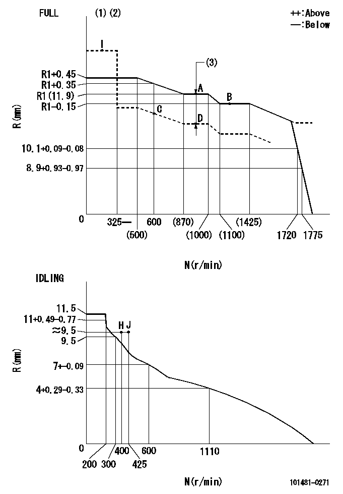
N:Pump speed
R:Rack position (mm)
(1)Torque cam stamping: T1
(2)Tolerance for racks not indicated: +-0.05mm.
(3)Boost compensator stroke: BCL
----------
T1=J45 BCL=1.05+-0.1mm
----------
----------
T1=J45 BCL=1.05+-0.1mm
----------
Speed control lever angle

F:Full speed
I:Idle
(1)Stopper bolt set position 'H'
----------
----------
a=7.5deg+-5deg b=33deg+-3deg
----------
----------
a=7.5deg+-5deg b=33deg+-3deg
Stop lever angle
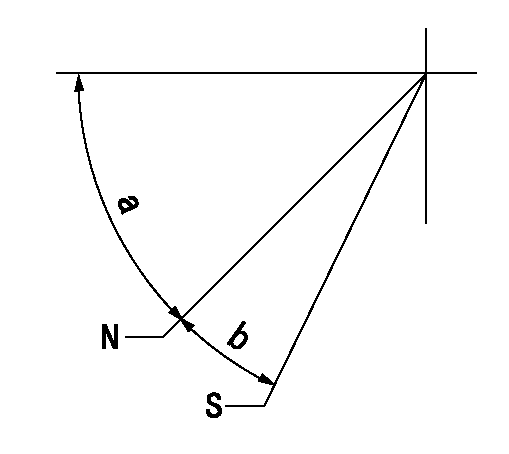
N:Pump normal
S:Stop the pump.
----------
----------
a=45deg+-5deg b=29deg+-5deg
----------
----------
a=45deg+-5deg b=29deg+-5deg
0000001501 ACS

(A) Set screw
(B) Push rod 1
(C) Push rod 2
(D) Cover
1. Aneroid compensator unit adjustment
(1)Select the push rod 2 to obtain L2.
(2)Screw in (A) to obtain L1.
2. Adjustment when mounting the governor.
(1)Set the speed of the pump to N1 r/min and fix the control lever at the full set position.
(2)Screw in the aneroid compensator to obtain the performance shown in the graph above.
(3)As there is hysterisis, measure when the absolute pressure drops.
(4)Hysterisis must not exceed rack position = h1.
----------
N1=950r/min L1=(1.5)mm L2=24+-0.5mm h1=0.15mm
----------
Ra=R1(11.9)mm Rb=R1-0.4mm Pa=86.6+-2.7kPa(650+-20mmHg) Pb=74.6+0.7kPa(560+-5mmHg) Q1=77+-1cm3/1000st Q2=(68)+-2cm3/1000st
----------
N1=950r/min L1=(1.5)mm L2=24+-0.5mm h1=0.15mm
----------
Ra=R1(11.9)mm Rb=R1-0.4mm Pa=86.6+-2.7kPa(650+-20mmHg) Pb=74.6+0.7kPa(560+-5mmHg) Q1=77+-1cm3/1000st Q2=(68)+-2cm3/1000st
0000001601 ACS
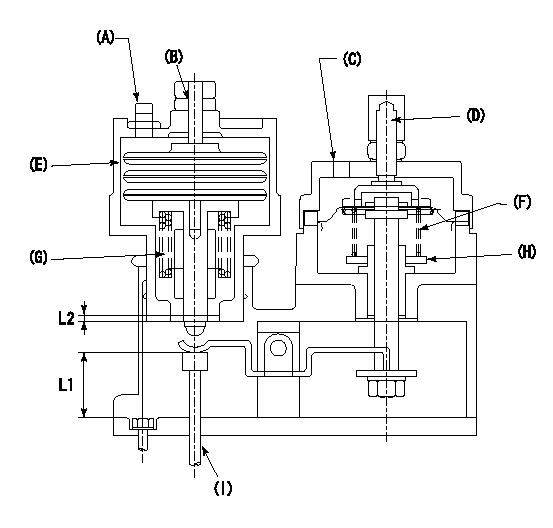
(A) Aneroid compensator
(B) Set screw
(C) Boost pressure inlet
(D) Rack positioning screw
(E): Aneroid compensator main body
(F) Boost compensator spring
(G): Aneroid compensator spring
(H): Adjusting notch
(I) Push rod
1. Instructions for adjusting the boost compensator with the aneroid compensator
(1)Select a pushrod to obtain L1 at full boost.
(2)Remove the aneroid compensator main body.
(3)Adjust the booster compensator stroke by turning the screw at (D.
(4)Adjust the beginning of boost compensator operation by turning the notch at (H).
(5)Install the aneroid compensator at full boost state.
(6)Turn (B)'s set screw so that the distance between the snapring and the body is L2.
(7)Screw in the aneroid compensator main body and adjust the point where it comes into play.
----------
L1=24+-0.5mm L2=1.5+-0.5mm
----------
----------
L1=24+-0.5mm L2=1.5+-0.5mm
----------
Timing setting

(1)Pump vertical direction
(2)Position of gear mark 'CC' at No 1 cylinder's beginning of injection
(3)B.T.D.C.: aa
(4)-
----------
aa=11deg
----------
a=(100deg)
----------
aa=11deg
----------
a=(100deg)
Information:
Do not operate the machine if any guards or covers are missing or inadequately secured. Personnel could be seriously injured or machine damage may occur.
Observe the safe working load limits of all lifting and blocking devices and keep a safe distance from suspended/blocked loads. Personnel may be seriously injured or killed by falling loads.
Reference Section
Refer to Service Magazine, M0082326, "Diesel Exhaust Fluid (DEF) Contamination on C4.4 Machine Engines".Refer to Service Magazine, M0096547, "Diesel Exhaust Fluid (DEF) Pump Filter Maintenance on Certain C4.4 Machine Engines".Refer to Special Instruction, M0096185, "Diesel Exhaust Fluid (DEF) Pump Diesel Contamination Test on Certain C4.4 Engines".Problem
There have been instances of returned DEF pumps that have no fault found or indicating contamination.Resolution
Complete the form below and attach to any SIMSi claim in addition to a Product Status Report (PSR) from before any troubleshooting was performed or any diagnostic codes were cleared.
Use the electronic service tool to download a PSR with Histograms.
Enter the diagnostic codes that require troubleshooting: ___
Perform the correct troubleshooting procedure for any active diagnostic codes. Refer to Troubleshooting, Diagnostic Trouble Codes.
If the troubleshooting procedure requests that the DEF is tested for contamination or concentration , record the results in Table 1 and Table 2.
For other DEF-related troubleshooting procedures, follow the applicable troubleshooting steps and record the results in Table 3.
Table 1
DEF Contamination
Step Instruction Completed Result Units
1 Perform the test procedure for DEF contamination. Refer to Systems Operation, Testing and Adjusting, Diesel Exhaust Fluid Quality - Test.
2 Compensator measurements. Refer to Special Instruction, M0096185, "Diesel Exhaust Fluid (DEF) Pump Diesel Contamination Test on Certain C4.4 Engines".
Diameter (A) mm
Length (B) mm
3 If contamination is present, confirm that DEF system has been flushed. Refer to Systems Operation, Testing and Adjusting, Diesel Exhaust Fluid Tank - Flush
Table 2
DEF Concentration
Step Instruction Completed Result Units
1 Perform the test procedure for DEF concentration. Refer to Systems Operation, Testing and Adjusting, Diesel Exhaust Fluid Quality - Test. %
2 If the DEF concentration is out of specification, confirm that the DEF tank has been drained and filled with the correct specification of DEF. Refer to Operation and Maintenance Manual, Diesel Exhaust Fluid - Fill.
Table 3
DEF Troubleshooting
Step Instruction Completed Result Units
1 Latest engine and Dosing Control Unit (DCU) software has been installed. Refer to Troubleshooting, ECM Software - Install.
2 DEF lines have been checked for restrictions.
3 DEF pump has been checked for restrictions.
4 DEF injector has been checked for restrictions.
5 DEF lines have been inspected for leaks.
6 Confirm the DEF pressure. Refer to Troubleshooting, DEF Pressure Does Not Respond. kPa
7 DEF dosing system accuracy test has been performed. Refer to Troubleshooting, Aftertreatment SCR System Dosing - Test.
8 DEF pump filter replaced.
9 "Aftertreatment System Functional Test" performed. Refer to Troubleshooting, Service Tool Features.