Information injection-pump assembly
ZEXEL
101481-0231
1014810231
ISUZU
8971320501
8971320501
Rating:
Service parts 101481-0231 INJECTION-PUMP ASSEMBLY:
1.
_
6.
COUPLING PLATE
7.
COUPLING PLATE
8.
_
9.
_
11.
Nozzle and Holder
8-97042-322-1
12.
Open Pre:MPa(Kqf/cm2)
13.2{135}
15.
NOZZLE SET
Cross reference number
ZEXEL
101481-0231
1014810231
ISUZU
8971320501
8971320501
Zexel num
Bosch num
Firm num
Name
Calibration Data:
Adjustment conditions
Test oil
1404 Test oil ISO4113 or {SAEJ967d}
1404 Test oil ISO4113 or {SAEJ967d}
Test oil temperature
degC
40
40
45
Nozzle and nozzle holder
105780-8140
Bosch type code
EF8511/9A
Nozzle
105780-0000
Bosch type code
DN12SD12T
Nozzle holder
105780-2080
Bosch type code
EF8511/9
Opening pressure
MPa
17.2
Opening pressure
kgf/cm2
175
Injection pipe
Outer diameter - inner diameter - length (mm) mm 6-2-600
Outer diameter - inner diameter - length (mm) mm 6-2-600
Overflow valve
131424-4920
Overflow valve opening pressure
kPa
127
107
147
Overflow valve opening pressure
kgf/cm2
1.3
1.1
1.5
Tester oil delivery pressure
kPa
157
157
157
Tester oil delivery pressure
kgf/cm2
1.6
1.6
1.6
Direction of rotation (viewed from drive side)
Right R
Right R
Injection timing adjustment
Direction of rotation (viewed from drive side)
Right R
Right R
Injection order
1-3-4-2
Pre-stroke
mm
2.8
2.75
2.85
Rack position
Point A R=A
Point A R=A
Beginning of injection position
Drive side NO.1
Drive side NO.1
Difference between angles 1
Cal 1-3 deg. 90 89.5 90.5
Cal 1-3 deg. 90 89.5 90.5
Difference between angles 2
Cal 1-4 deg. 180 179.5 180.5
Cal 1-4 deg. 180 179.5 180.5
Difference between angles 3
Cyl.1-2 deg. 270 269.5 270.5
Cyl.1-2 deg. 270 269.5 270.5
Injection quantity adjustment
Adjusting point
-
Rack position
11.7
Pump speed
r/min
950
950
950
Average injection quantity
mm3/st.
73
71.4
74.6
Max. variation between cylinders
%
0
-4
4
Basic
*
Fixing the rack
*
Standard for adjustment of the maximum variation between cylinders
*
Injection quantity adjustment_02
Adjusting point
H
Rack position
9.5+-0.5
Pump speed
r/min
400
400
400
Average injection quantity
mm3/st.
13
11.7
14.3
Max. variation between cylinders
%
0
-14
14
Fixing the rack
*
Standard for adjustment of the maximum variation between cylinders
*
Injection quantity adjustment_03
Adjusting point
A
Rack position
R1(11.7)
Pump speed
r/min
950
950
950
Average injection quantity
mm3/st.
73
72
74
Basic
*
Fixing the lever
*
Boost pressure
kPa
62.7
62.7
Boost pressure
mmHg
470
470
Injection quantity adjustment_04
Adjusting point
B
Rack position
R1-0.15
Pump speed
r/min
1375
1375
1375
Average injection quantity
mm3/st.
75.5
71.5
79.5
Fixing the lever
*
Boost pressure
kPa
62.7
62.7
Boost pressure
mmHg
470
470
Injection quantity adjustment_05
Adjusting point
C
Rack position
(R1-0.35
)
Pump speed
r/min
600
600
600
Average injection quantity
mm3/st.
59
55
63
Fixing the lever
*
Boost pressure
kPa
0
0
0
Boost pressure
mmHg
0
0
0
Injection quantity adjustment_06
Adjusting point
I
Rack position
-
Pump speed
r/min
150
150
150
Average injection quantity
mm3/st.
93
93
109
Fixing the lever
*
Boost pressure
kPa
0
0
0
Boost pressure
mmHg
0
0
0
Boost compensator adjustment
Pump speed
r/min
950
950
950
Rack position
R1-0.7
Boost pressure
kPa
8
6.7
9.3
Boost pressure
mmHg
60
50
70
Boost compensator adjustment_02
Pump speed
r/min
950
950
950
Rack position
R1(11.7)
Boost pressure
kPa
49.3
49.3
49.3
Boost pressure
mmHg
370
370
370
Timer adjustment
Pump speed
r/min
600--
Advance angle
deg.
0
0
0
Remarks
Start
Start
Timer adjustment_02
Pump speed
r/min
500
Advance angle
deg.
0.5
Timer adjustment_03
Pump speed
r/min
1500
Advance angle
deg.
2.5
2
3
Remarks
Finish
Finish
Test data Ex:
Governor adjustment
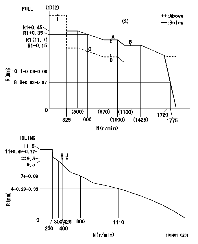
N:Pump speed
R:Rack position (mm)
(1)Torque cam stamping: T1
(2)Tolerance for racks not indicated: +-0.05mm.
(3)Boost compensator stroke: BCL
----------
T1=J45 BCL=0.7+-0.1mm
----------
----------
T1=J45 BCL=0.7+-0.1mm
----------
Speed control lever angle

F:Full speed
I:Idle
(1)Stopper bolt setting
----------
----------
a=7.5deg+-5deg b=33deg+-3deg
----------
----------
a=7.5deg+-5deg b=33deg+-3deg
Stop lever angle
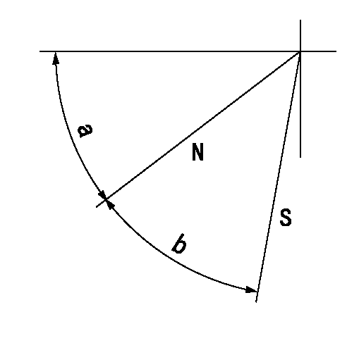
N:Pump normal
S:Stop the pump.
----------
----------
a=45deg+-5deg b=29deg+-5deg
----------
----------
a=45deg+-5deg b=29deg+-5deg
0000001501 ACS

(A) Set screw
(B) Push rod 1
(C) Push rod 2
(D) Cover
1. Aneroid compensator unit adjustment
(1)Select the push rod 2 to obtain L2.
(2)Screw in (A) to obtain L1.
2. Adjustment when mounting the governor.
(1)Set the speed of the pump to N1 r/min and fix the control lever at the full set position.
(2)Screw in the aneroid compensator to obtain the performance shown in the graph above.
(3)As there is hysterisis, measure when the absolute pressure drops.
(4)Hysterisis must not exceed rack position = h1.
----------
N1=950r/min L1=(1.5)mm L2=24+-0.5mm h1=0.15mm
----------
Ra=R1(11.7)mm Rb=R1-0.25mm Pa=74.6+-2.7kPa(560+-20mmHg) Pb=61.6+-0.7kPa(462+-5mmHg) Q1=73+-1cm3/1000st Q2=(66.5)+-2cm3/1000st
----------
N1=950r/min L1=(1.5)mm L2=24+-0.5mm h1=0.15mm
----------
Ra=R1(11.7)mm Rb=R1-0.25mm Pa=74.6+-2.7kPa(560+-20mmHg) Pb=61.6+-0.7kPa(462+-5mmHg) Q1=73+-1cm3/1000st Q2=(66.5)+-2cm3/1000st
0000001601 ACS
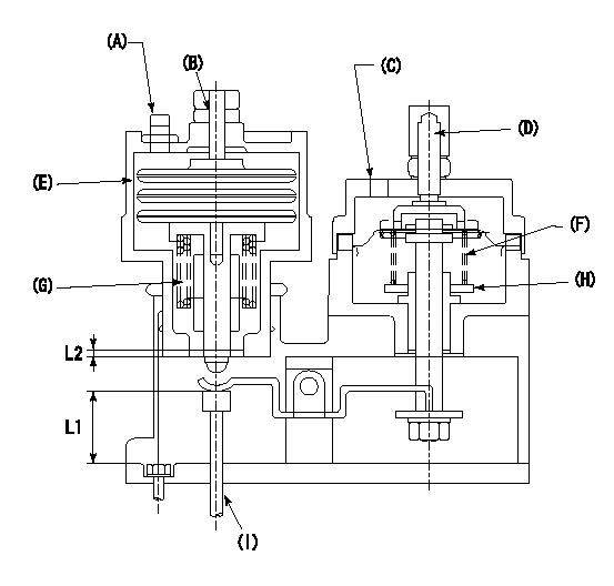
(A) Aneroid compensator
(B) Set screw
(C) Boost pressure inlet
(D) Rack positioning screw
(E): Aneroid compensator main body
(F) Boost compensator spring
(G): Aneroid compensator spring
(H): Adjusting notch
(I) Push rod
1. Instructions for adjusting the boost compensator with the aneroid compensator
(1)Select a pushrod to obtain L1 at full boost.
(2)Remove the aneroid compensator main body.
(3)Adjust the booster compensator stroke by turning the screw at (D.
(4)Adjust the beginning of boost compensator operation by turning the notch at (H).
(5)Install the aneroid compensator at full boost state.
(6)Turn (B)'s set screw so that the distance between the snapring and the body is L2.
(7)Screw in the aneroid compensator main body and adjust the point where it comes into play.
----------
L1=24+-0.5mm L2=1.5+-0.5mm
----------
----------
L1=24+-0.5mm L2=1.5+-0.5mm
----------
Timing setting

(1)Pump vertical direction
(2)Position of gear mark 'CC' at No 1 cylinder's beginning of injection
(3)B.T.D.C.: aa
(4)-
----------
aa=11deg
----------
a=(100deg)
----------
aa=11deg
----------
a=(100deg)
Information:
Climbing equipment may be required to access this service point. Refer to the Operation and Maintenance Manual, "Mounting and Dismounting" topic for safety information.
Before servicing/performing maintenance on the machine, electrical power must be physically disconnected; battery plugs must be disconnected from the batteries, or the trailing cable must be unplugged, and warning tags and padlocks shall be applied by a certified electrician. Certified electricians shall perform or direct any electrical work, including any energized testing, repair work in controllers, motors, or other approved compartments, and shall insure that all compartments are properly closed and inspected prior to re-energization. All applicable lock out and tag out procedures must be followed.
Observe the safe working load limits of all lifting and blocking devices and keep a safe distance from suspended/blocked loads. Personnel may be seriously injured or killed by falling loads.
Required Parts
The LFI component PMMA surface characteristics are as follows
Cover Layer
Gloss
Scratch resistance
Weather resistance
Color Layer
Coloring
Ultraviolet resistance
Carrier Layer
Adhesion to backing foam
Heat deformation resistance
Backing Foam
Strength
Stability
Impact resistance
Heat deformation resistanceRepair Procedure
Illustration 1 g06509785
Simulated punch hole
Illustration 2 g06509787
Location to grind off backside
Grind material off from backside
Illustration 3 g06509788
Fiberglass mat and plastic filler
Place fiberglass mat and place plastic filler on backside
Illustration 4 g06509791
Location to grind off exterior side
Grind material off from exterior side
Illustration 5 g06509792
Location to add filler on exterior side
Fill hole on exterior side with plastic filler
Illustration 6 g06510059
Exterior surface to grind flat
Grind plastic filler on exterior to achieve flat surface
Illustration 7 g06510075
Area to apply plasticiser
Apply plastic filler with plasticiser to the exterior
Illustration 8 g06510079
Exterior area to grind plastic filler containing plasticiser
Grind plastic filler containing plasticiser and also area to be painted
Illustration 9 g06510084
Exterior plastic surface painted with primer
Paint exterior with primer for plastic surfaces
Illustration 10 g06510086
Exterior plastic surface painted with top coat
Paint exterior with top coat