Information injection-pump assembly
ZEXEL
101472-3780
1014723780
KOMATSU
6144751105
6144751105
Rating:
Service parts 101472-3780 INJECTION-PUMP ASSEMBLY:
1.
_
5.
AUTOM. ADVANCE MECHANIS
6.
COUPLING PLATE
7.
COUPLING PLATE
8.
_
9.
_
11.
Nozzle and Holder
6142-12-3300
12.
Open Pre:MPa(Kqf/cm2)
11.8{120}
15.
NOZZLE SET
Include in #1:
101472-3780
as INJECTION-PUMP ASSEMBLY
Include in #2:
104749-1040
as _
Cross reference number
ZEXEL
101472-3780
1014723780
KOMATSU
6144751105
6144751105
Zexel num
Bosch num
Firm num
Name
Calibration Data:
Adjustment conditions
Test oil
1404 Test oil ISO4113 or {SAEJ967d}
1404 Test oil ISO4113 or {SAEJ967d}
Test oil temperature
degC
40
40
45
Nozzle and nozzle holder
105780-8140
Bosch type code
EF8511/9A
Nozzle
105780-0000
Bosch type code
DN12SD12T
Nozzle holder
105780-2080
Bosch type code
EF8511/9
Opening pressure
MPa
17.2
Opening pressure
kgf/cm2
175
Injection pipe
Outer diameter - inner diameter - length (mm) mm 6-2-600
Outer diameter - inner diameter - length (mm) mm 6-2-600
Tester oil delivery pressure
kPa
157
157
157
Tester oil delivery pressure
kgf/cm2
1.6
1.6
1.6
Direction of rotation (viewed from drive side)
Right R
Right R
Injection timing adjustment
Direction of rotation (viewed from drive side)
Right R
Right R
Injection order
1-2-4-3
Pre-stroke
mm
2.2
2.15
2.25
Beginning of injection position
Drive side NO.1
Drive side NO.1
Difference between angles 1
Cyl.1-2 deg. 90 89.5 90.5
Cyl.1-2 deg. 90 89.5 90.5
Difference between angles 2
Cal 1-4 deg. 180 179.5 180.5
Cal 1-4 deg. 180 179.5 180.5
Difference between angles 3
Cal 1-3 deg. 270 269.5 270.5
Cal 1-3 deg. 270 269.5 270.5
Injection quantity adjustment
Adjusting point
A
Rack position
11.1
Pump speed
r/min
700
700
700
Average injection quantity
mm3/st.
43
42
44
Max. variation between cylinders
%
0
-2
2
Basic
*
Fixing the lever
*
Injection quantity adjustment_02
Adjusting point
B
Rack position
8.8+-0.5
Pump speed
r/min
350
350
350
Average injection quantity
mm3/st.
9
8.2
9.8
Max. variation between cylinders
%
0
-15
15
Fixing the rack
*
Test data Ex:
Governor adjustment
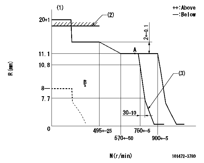
N:Pump speed
R:Rack position (mm)
(1)Target notch: K
(2)RACK CAP: R1
(3)Idle sub spring setting: L1.
----------
K=7 R1=18+1mm L1=7.7-0.5mm
----------
----------
K=7 R1=18+1mm L1=7.7-0.5mm
----------
Speed control lever angle
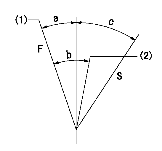
F:Full speed
S:Stop
(1)Set the pump speed at aa. ( At delivery )
(2)Set the pump speed at bb.
----------
aa=900r/min bb=750r/min
----------
a=4deg+-5deg b=6deg+-5deg c=32deg+-3deg
----------
aa=900r/min bb=750r/min
----------
a=4deg+-5deg b=6deg+-5deg c=32deg+-3deg
Stop lever angle

N:Pump normal
S:Stop the pump.
----------
----------
a=26.5deg+-5deg b=53deg+-5deg
----------
----------
a=26.5deg+-5deg b=53deg+-5deg
Timing setting
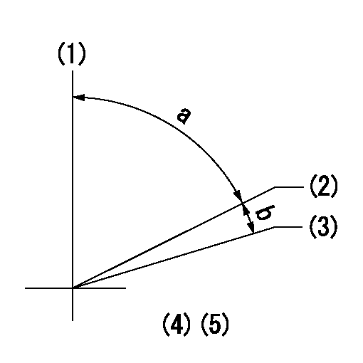
(1)Pump vertical direction
(2)Position of key groove at No 1 cylinder's beginning of injection
(3)Stamp aligning marks on the pump housing flange.
(4)-
(5)-
----------
----------
a=50deg24min+-3deg b=9deg36min+-30min
----------
----------
a=50deg24min+-3deg b=9deg36min+-30min
Information:
Introduction
The EPA has mandated that a DEF quality sensor must be installed on all engines built in 2017 or after. This new DEF quality sensor is integrated into the DEF header inside the DEF tank. The new style DEF header utilizes CAN C communication, so the wiring to the DEF header has been slightly modified on product going forward. However, the DCU remains compatible to both setups with the latest 507-7605 Engine Software. As part of the DEF quality sensor implementation, a new configuration parameter setting is used on the engine ECM in Cat® Electronic Technician (ET) to identify whether a DEF quality sensor is "installed" or "not installed". Below are some different fault codes for incompatible hardware and configuration setting as well as different service scenarios that may be encountered with this change and how to resolve any issues in these particular service scenarios. In addition to this Special Instruction, there is a video detailing these changes posted on Cat Channel 1.Channel1 Video
Note: A CWS login is required to access Caterpillar Channel1. Scan the QR code below with a QR enabled device or copy the link that follows.
Illustration 1 g06462430Reference: For more information, refer to "Diesel Exhaust Fluid Quality Sensor" on Caterpillar Channel1.https://channel1.mediaspace.kaltura.com/media/0_qyokrphe
Fault Codes When Parts/Settings Are Not Compatible
DEF quality header not installed but configuration set to installed.
Table 1
J1939 Code and Description CDL Code and Description
1235-9
J1939 Network #3 : Abnormal Update Rate 5856-9
J1939 Network #3 : Abnormal Update Rate DEF quality header installed but configuration set to not installed.
Table 2
J1939 Code and Description CDL Code and Description
1761-3
Aftertreatment 1 Diesel Exhaust Fluid Tank Level : Voltage Above Normal 3130-3
Aftertreatment #1 SCR Catalyst Reagent Tank #1 Level Sensor : Voltage Above Normal
3031-3
Aftertreatment 1 Diesel Exhaust Fluid Tank Temperature : Voltage Above Normal 3134-3
Aftertreatment #1 SCR Catalyst Reagent Tank #1 Temperature Sensor : Voltage Above Normal DEF Quality Sensor Service Scenarios
Listed below are the different examples of when the DEF Quality Sensor and associated components are needed.Replacement Industrial Engine (Built in 2016 or Before)
If these engines are replaced with an engine built in 2017 or after, the following updates will be required:
Updating to a DEF Quality Sensor by installing a new DEF Header
Wiring Harness
DCU Software
Change configuration status to "Installed" in Cat ETReplacement Machine Engine (Built in 2016 or Before)
If this engine is replaced with an engine built in 2016 or a previous Engine Arrangement Complete (EAC) engine, no other changes are needed.Confirm that the "DEF Quality Sensor" configuration is set to "Not Installed" in Cat ET.Replacement Machine Engine (Built in 2016 or Before)
If the engine is replaced with the latest EAC the following updates will be required:
Update to a DEF Quality Sensor by installing a new DEF header
Wiring harness
DCU Software
Change configuration status to "Installed" in Cat ETReplacement Engine (Built in 2017 or After)
Replace the engine with the latest EAC.Installing the DEF Quality Sensor on Engines Built in 2016 or Before
If installing the DEF Quality Sensor on engine built in 2016 or before, the following must be updated as well:
DCU software update
PETU
