Information injection-pump assembly
ZEXEL
101472-3460
1014723460
KOMATSU
6141751100
6141751100

Rating:
Service parts 101472-3460 INJECTION-PUMP ASSEMBLY:
1.
_
3.
GOVERNOR
4.
SUPPLY PUMP
5.
AUTOM. ADVANCE MECHANIS
6.
COUPLING PLATE
7.
COUPLING PLATE
8.
_
9.
_
11.
Nozzle and Holder
6140-11-3103
12.
Open Pre:MPa(Kqf/cm2)
22.1{225}
15.
NOZZLE SET
Cross reference number
ZEXEL
101472-3460
1014723460
KOMATSU
6141751100
6141751100
Zexel num
Bosch num
Firm num
Name
101472-3460
6141751100 KOMATSU
INJECTION-PUMP ASSEMBLY
4D92 *
4D92 *
Calibration Data:
Adjustment conditions
Test oil
1404 Test oil ISO4113 or {SAEJ967d}
1404 Test oil ISO4113 or {SAEJ967d}
Test oil temperature
degC
40
40
45
Nozzle
105015-2910
Nozzle holder
105031-3410
Opening pressure
MPa
22.1
Opening pressure
kgf/cm2
225
Injection pipe
Outer diameter - inner diameter - length (mm) mm 6-1.6-500
Outer diameter - inner diameter - length (mm) mm 6-1.6-500
Overflow valve
132424-0620
Overflow valve opening pressure
kPa
157
123
191
Overflow valve opening pressure
kgf/cm2
1.6
1.25
1.95
Tester oil delivery pressure
kPa
157
157
157
Tester oil delivery pressure
kgf/cm2
1.6
1.6
1.6
Direction of rotation (viewed from drive side)
Right R
Right R
Injection timing adjustment
Direction of rotation (viewed from drive side)
Right R
Right R
Injection order
1-2-4-3
Pre-stroke
mm
2.7
2.65
2.75
Rack position
R=10.5
Beginning of injection position
Drive side NO.1
Drive side NO.1
Difference between angles 1
Cyl.1-2 deg. 90 89.5 90.5
Cyl.1-2 deg. 90 89.5 90.5
Difference between angles 2
Cal 1-4 deg. 180 179.5 180.5
Cal 1-4 deg. 180 179.5 180.5
Difference between angles 3
Cal 1-3 deg. 270 269.5 270.5
Cal 1-3 deg. 270 269.5 270.5
Injection quantity adjustment
Adjusting point
A
Rack position
12
Pump speed
r/min
700
700
700
Average injection quantity
mm3/st.
53
52
54
Max. variation between cylinders
%
0
-2
2
Basic
*
Fixing the rack
*
Injection quantity adjustment_02
Adjusting point
C
Rack position
9.5
Pump speed
r/min
400
400
400
Average injection quantity
mm3/st.
14
12.5
15.5
Max. variation between cylinders
%
0
-10
10
Fixing the rack
*
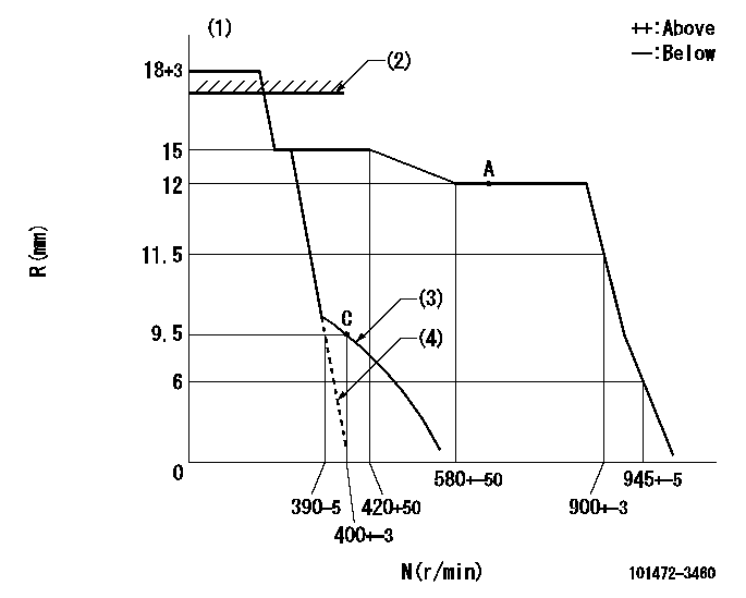
Test data Ex:
Governor adjustment

N:Pump speed
R:Rack position (mm)
(1)Target notch: K
(2)RACK LIMIT: RAL
(3)Set idle sub-spring
(4)Main spring only
----------
K=5 RAL=18+-1mm
----------
----------
K=5 RAL=18+-1mm
----------
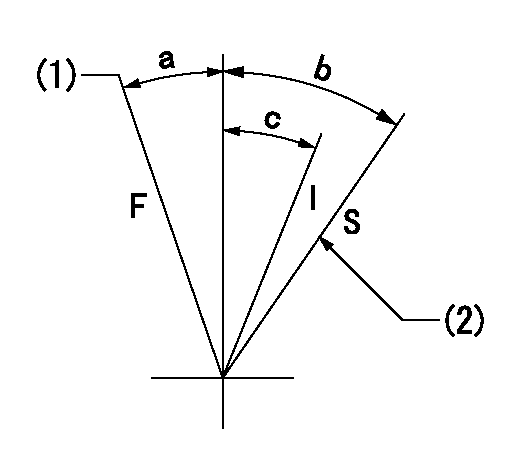
Speed control lever angle

F:Full speed
I:Idle
S:Stop
(1)Speed set at aa (setting at shipping)
(2)Set the stop side stopper bolt at the stop position.
----------
aa=900r/min
----------
a=9deg+-5deg b=32deg+-3deg c=16deg+-3deg
----------
aa=900r/min
----------
a=9deg+-5deg b=32deg+-3deg c=16deg+-3deg
Information:
Do not operate or work on this product unless you have read and understood the instruction and warnings in the relevant Operation and Maintenance Manuals and relevant service literature. Failure to follow the instructions or heed the warnings could result in injury or death. Proper care is your responsibility.
The following changes are adaptable to the products within the listed serial numbers, and are effective with all products after the listed serial numbers.Updating to the new components is recommended at the Planned Component Replacement (PCR) for all engines equipped with the 4x4 turbocharger configuration.
Illustration 1 g06495375
(1) New 588-3516 Support As
(D1) Oil Lubrication Jet Orifice 0.8 mm (0.032 inch)
Illustration 2 g06495382
(B) Former 525-1901 Support As
(D2) 1.6 mm (0.063 inch)The new 588-3516 Support As has an oil lubrication jet orifice that has been reduced to 0.8 mm (0.032 inch) from the jet orifice size of 1.6 mm (0.063 inch) in the former support assembly.
Illustration 3 g06495384
(2) New 582-8173 Wiring Harness
Illustration 4 g06495387
(B) Former 415-1169 Wiring HarnessThe new injector wiring harness has the closest zip tie assembly removed as shown in the illustrations above. The improved routing allows for increased harness clearance to the oil lubrication orifice.The table below contains the new part numbers for this change.
Table 1
Required Parts
Item Qty New Part Number Part Name Former Part Number
1 20 588-3516 Support As 525-1901
2 20 582-8173 Wiring Harness 415-1169 The table below contains the effective engine serial numbers for this change.
Table 2
Effective Engine Serial Numbers
S/N:4X41023-UP
S/N:L4G1032-UP
Have questions with 101472-3460?
Group cross 101472-3460 ZEXEL
Komatsu
101472-3460
6141751100
INJECTION-PUMP ASSEMBLY
4D92
4D92