Information injection-pump assembly
ZEXEL
101471-0201
1014710201
ISUZU
5156012262
5156012262
Rating:
Service parts 101471-0201 INJECTION-PUMP ASSEMBLY:
1.
_
6.
COUPLING PLATE
7.
COUPLING PLATE
8.
_
9.
_
11.
Nozzle and Holder
5-15300-097-0
12.
Open Pre:MPa(Kqf/cm2)
11.8{120}

15.
NOZZLE SET
Cross reference number
ZEXEL
101471-0201
1014710201
ISUZU
5156012262
5156012262
Zexel num
Bosch num
Firm num
Name
101471-0201
5156012262 ISUZU
INJECTION-PUMP ASSEMBLY
4BC1 * K
4BC1 * K
Calibration Data:
Adjustment conditions
Test oil
1404 Test oil ISO4113 or {SAEJ967d}
1404 Test oil ISO4113 or {SAEJ967d}
Test oil temperature
degC
40
40
45
Nozzle and nozzle holder
105780-8140
Bosch type code
EF8511/9A
Nozzle
105780-0000
Bosch type code
DN12SD12T
Nozzle holder
105780-2080
Bosch type code
EF8511/9
Opening pressure
MPa
17.2
Opening pressure
kgf/cm2
175
Injection pipe
Outer diameter - inner diameter - length (mm) mm 6-2-600
Outer diameter - inner diameter - length (mm) mm 6-2-600
Tester oil delivery pressure
kPa
157
157
157
Tester oil delivery pressure
kgf/cm2
1.6
1.6
1.6
Direction of rotation (viewed from drive side)
Right R
Right R
Injection timing adjustment
Direction of rotation (viewed from drive side)
Right R
Right R
Injection order
1-3-4-2
Pre-stroke
mm
2.2
2.15
2.25
Rack position
Point B R=B
Point B R=B
Beginning of injection position
Drive side NO.1
Drive side NO.1
Difference between angles 1
Cal 1-3 deg. 90 89.5 90.5
Cal 1-3 deg. 90 89.5 90.5
Difference between angles 2
Cal 1-4 deg. 180 179.5 180.5
Cal 1-4 deg. 180 179.5 180.5
Difference between angles 3
Cyl.1-2 deg. 270 269.5 270.5
Cyl.1-2 deg. 270 269.5 270.5
Injection quantity adjustment
Adjusting point
A
Rack position
11.6
Pump speed
r/min
500
500
500
Average injection quantity
mm3/st.
47.3
45.5
49.1
Max. variation between cylinders
%
0
-4
4
Fixing the rack
*
Injection quantity adjustment_02
Adjusting point
B
Rack position
11
Pump speed
r/min
1750
1750
1750
Average injection quantity
mm3/st.
52.5
51.5
53.5
Max. variation between cylinders
%
0
-2.5
2.5
Basic
*
Fixing the rack
*
Injection quantity adjustment_03
Adjusting point
C
Rack position
8.3
Pump speed
r/min
300
300
300
Average injection quantity
mm3/st.
8.5
7.1
9.9
Max. variation between cylinders
%
0
-14
14
Fixing the rack
*
Injection quantity adjustment_04
Adjusting point
D
Rack position
16+-0.5
Pump speed
r/min
150
150
150
Average injection quantity
mm3/st.
89
84
94
Fixing the rack
*
Remarks
Excess fuel for starting.
Excess fuel for starting.
Timer adjustment
Pump speed
r/min
500
Advance angle
deg.
0.5
Timer adjustment_02
Pump speed
r/min
700
Advance angle
deg.
1
Timer adjustment_03
Pump speed
r/min
1000
Advance angle
deg.
1.5
1
2
Timer adjustment_04
Pump speed
r/min
1400
Advance angle
deg.
4
3.5
4.5
Timer adjustment_05
Pump speed
r/min
1750
Advance angle
deg.
6
6
7
Remarks
Finish
Finish
Test data Ex:
Governor adjustment
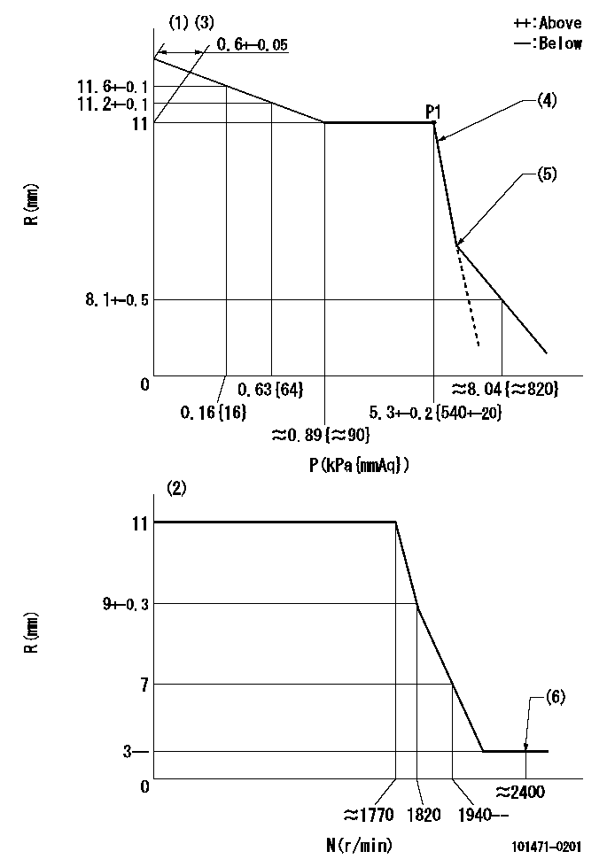
N:Pump speed
R:Rack position (mm)
P:Negative pressure
(1)Pneumatic governor
(2)Mechanical governor
(3)Acting negative pressure: P1
(4)Adjustment speed N1
(5)Beginning of idle sub spring operation: L1
(6)Injection quantity Q = Q1 or less
----------
N1=500r/min L1=9.5+-0.5mm Q1=3mm3/st
----------
----------
N1=500r/min L1=9.5+-0.5mm Q1=3mm3/st
----------
Timing setting

(1)Pump vertical direction
(2)Position of gear mark 'CC' at No 1 cylinder's beginning of injection
(3)B.T.D.C.: aa
(4)-
----------
aa=8deg
----------
a=(100deg)
----------
aa=8deg
----------
a=(100deg)
Information:
General Contamination Control Recommendations or Practices
Maintaining a low contamination level can reduce down time and can control the maintenance cost of the engine. The productive life as well as the reliability of components and fluid systems is often increased as a result of proper contamination control practices.The following are general guidelines for controlling contaminants.
Refer to the Recommendations for Fuel Systems in this chapter for recommended fuel cleanliness levels and guidelines.
Refer to the engine Operation and Maintenance Manual for the required maintenance for all engine fluids.
When you add oil to an engine, use engine oil filters of 12 microns absolute efficiency. Ensure that the oil temperature is 20° C (68° F) or higher.
Perform scheduled S O S Services Oil Analysis for contamination in order to maintain the recommended ISO cleanliness level of fill and machine fluids. Refer to the S O S Oil Analysis section in this Special Publication. The particle count analysis can be performed by your Cat dealer. Particle count can be conducted during the scheduled S O S Services Oil Analysis for the compartment. Extra oil samples are not required for the particle count sampling.
Use only coolants that are recommended by Cat for your machine. Follow the recommended maintenance procedure for the cooling system in the Operation and Maintenance Manual for your machine.
Maintain the engine air filters and air intake system to avoid unwanted contaminant ingression.
Follow contamination control practices for the shop area, component/machine disassembly areas, parts, shop tools, test setups, test areas, storage areas and waste collection areas. Keep components clean during inspection, assembly, testing, and filling engines with clean fluids. Good practices will enhance component life and reduce downtime associated with contaminants. Your Cat dealer can provide details on proper contamination processes and practices.
Follow contamination control practices for the workplace and for the worksite. Maintaining clean oil fill fluids saves time and effort and ensures that fill fluids are at the proper cleanliness levels.
Use properly designed and maintained bulk storage fluids tanks.
Protect the fluids storage tanks from dirt and water entry by using 4 µm or less absolute efficiency breathers with the ability to remove water.
Keep the areas around the tanks filler necks clean of debris and water.
Drain the storage tanks from water and sediments frequently. The draining schedule depends on use of proper inlet and outlet filters, the use of 4 µm breathers with the ability to remove water, and following recommended contamination control practices. Based on the contamination control program followed, and/or on the fuel supplier recommendations, the storage tank draining schedule may be as frequent as daily until no water is present, and then can be extended to longer periods.
Install and maintain a properly designed and grounded filtration system. Filtration should include at the entry and at the dispensing point. Continuous bulk filtration may be required to ensure that dispensed oils meet the cleanliness target.
Cover, protect, and ensure cleanliness of all connection hoses, fittings, and dispensing nozzles.Note: Bulk fuel filtration units are available through your Cat dealer. Proper maintenance practices of
Have questions with 101471-0201?
Group cross 101471-0201 ZEXEL
Isuzu
101471-0201
5156012262
INJECTION-PUMP ASSEMBLY
4BC1
4BC1