Information injection-pump assembly
ZEXEL
101471-0150
1014710150
ISUZU
5156009213
5156009213
Rating:
Service parts 101471-0150 INJECTION-PUMP ASSEMBLY:
1.
_
4.
SUPPLY PUMP
6.
COUPLING PLATE
7.
COUPLING PLATE
8.
_
9.
_
11.
Nozzle and Holder
5-15300-097-0
12.
Open Pre:MPa(Kqf/cm2)
11.8{120}

15.
NOZZLE SET
Cross reference number
ZEXEL
101471-0150
1014710150
ISUZU
5156009213
5156009213
Zexel num
Bosch num
Firm num
Name
Calibration Data:
Adjustment conditions
Test oil
1404 Test oil ISO4113 or {SAEJ967d}
1404 Test oil ISO4113 or {SAEJ967d}
Test oil temperature
degC
40
40
45
Nozzle and nozzle holder
105780-8140
Bosch type code
EF8511/9A
Nozzle
105780-0000
Bosch type code
DN12SD12T
Nozzle holder
105780-2080
Bosch type code
EF8511/9
Opening pressure
MPa
17.2
Opening pressure
kgf/cm2
175
Injection pipe
Outer diameter - inner diameter - length (mm) mm 6-2-600
Outer diameter - inner diameter - length (mm) mm 6-2-600
Tester oil delivery pressure
kPa
157
157
157
Tester oil delivery pressure
kgf/cm2
1.6
1.6
1.6
Direction of rotation (viewed from drive side)
Right R
Right R
Injection timing adjustment
Direction of rotation (viewed from drive side)
Right R
Right R
Injection order
1-3-4-2
Pre-stroke
mm
2.2
2.15
2.25
Rack position
Point B R=B
Point B R=B
Beginning of injection position
Drive side NO.1
Drive side NO.1
Difference between angles 1
Cal 1-3 deg. 90 89.5 90.5
Cal 1-3 deg. 90 89.5 90.5
Difference between angles 2
Cal 1-4 deg. 180 179.5 180.5
Cal 1-4 deg. 180 179.5 180.5
Difference between angles 3
Cyl.1-2 deg. 270 269.5 270.5
Cyl.1-2 deg. 270 269.5 270.5
Injection quantity adjustment
Adjusting point
B
Rack position
11
Pump speed
r/min
1750
1750
1750
Average injection quantity
mm3/st.
52.5
51.5
53.5
Max. variation between cylinders
%
0
-2.5
2.5
Basic
*
Fixing the rack
*
Injection quantity adjustment_02
Adjusting point
C
Rack position
8.3
Pump speed
r/min
300
300
300
Average injection quantity
mm3/st.
8.5
7.1
9.9
Max. variation between cylinders
%
0
-14
14
Fixing the rack
*
Injection quantity adjustment_03
Adjusting point
D
Rack position
18++
Pump speed
r/min
150
150
150
Average injection quantity
mm3/st.
80
80
Fixing the rack
*
Remarks
Excess fuel for starting.
Excess fuel for starting.
Timer adjustment
Pump speed
r/min
500
Advance angle
deg.
0.5
Timer adjustment_02
Pump speed
r/min
700
Advance angle
deg.
1
Timer adjustment_03
Pump speed
r/min
1000
Advance angle
deg.
1.5
1
2
Timer adjustment_04
Pump speed
r/min
1400
Advance angle
deg.
4
3.5
4.5
Timer adjustment_05
Pump speed
r/min
1750
Advance angle
deg.
6
6
7
Remarks
Finish
Finish
Test data Ex:
Governor adjustment
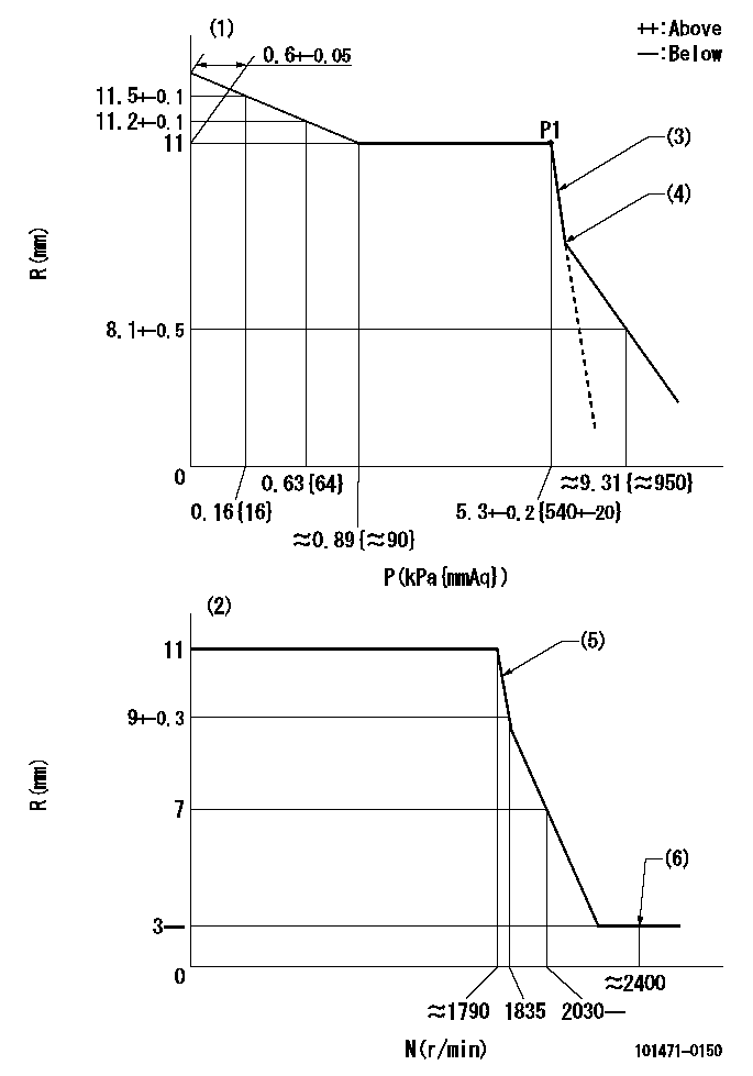
N:Pump speed
R:Rack position (mm)
P:Negative pressure
(1)Pneumatic governor
(2)Mechanical governor
(3)Adjustment speed N1
(4)Beginning of idle sub spring operation: L1
(5)Acting negative pressure: P1
(6)Injection quantity Q = Q1 or less
----------
N1=500r/min L1=9.3+-0.5mm Q1=3mm3/st
----------
----------
N1=500r/min L1=9.3+-0.5mm Q1=3mm3/st
----------
Timing setting

(1)Pump vertical direction
(2)Position of gear mark 'CC' at No 1 cylinder's beginning of injection
(3)B.T.D.C.: aa
(4)-
----------
aa=8deg
----------
a=(100deg)
----------
aa=8deg
----------
a=(100deg)
Information:
Bulk storage
Follow all local regulations covering bulk storage tanks. Follow proper tank construction guidelines. Tank volume typically should be 110% of planned capacity. Appropriately vent indoor tanks. Plan for control of overflow of the tank. Heat tanks that dispense DEF in cold climates.Bulk tank breathers should be fitted with filtration to keep airborne debris from entering the tank. Desiccant breathers should not be used because water will be absorbed, which potentially can alter DEF concentration.Handling
Follow all local regulations covering transport and handling. DEF transport temperature is recommended to be −5° C (23° F) to 25° C (77° F). All transfer equipment and intermediate containers should be used exclusively for DEF. Containers should not be reused for any other fluids. Ensure that transfer equipment is made from DEF-compatible materials. Recommended material for hoses and other non-metallic transfer equipment include:
Nitrile Rubber (NBR)
Fluoroelastomer (FKM)
Ethylene Propylene Diane Ionomer (EPDM)The condition of hoses and other nonmetallic items that are used with DEF should be monitored for signs of degradation. DEF leaks are easily recognizable by white urea crystals that accumulate at the site of the leak. Solid urea can be corrosive to galvanized or unalloyed steel, aluminum, copper, and brass. Leaks should be repaired immediately to avoid damage to surrounding hardware.Cleanliness
Contaminants can degrade the quality and life of DEF. Filtering DEF is recommended when dispensed into the DEF tank. Filters should be compatible with DEF and should be used exclusively with DEF. Check with the filter supplier to confirm compatibility with DEF before using. Mesh-type filters using compatible metals, such as stainless steel, are recommended. Paper (cellulose) media and some synthetic filter media are not recommended because of degradation during use.Care should be taken when dispensing DEF. Spills should be cleaned immediately. Machine or engine surfaces should be wiped clean and rinsed with water. Caution should be used when dispensing DEF near an engine that has recently been running.Note: Spilling DEF onto hot components may cause the release of ammonia vapors. Do not breathe ammonia vapors. Do not clean up any spills with bleach.Stability
DEF fluid is stable when stored and handled properly. The quality of DEF rapidly degrades when stored at high temperatures. The ideal storage temperature for DEF is between −9° C (15.8° F) and 25° C (77° F). DEF that is stored above 35° C (95° F) for longer than 1 month must be tested before use. Testing should evaluate Urea Percentage, Alkalinity as NH3 and Biuret content.The length of storage of DEF is listed in the following table:
Table 3
Storage Temperature Expected DEF Life
Below 25° C (77° F) 18 months
25° C (77° F) to 30° C (86° F) 12 months
30° C (86° F) to 35° C (95° F) 6 months
Above 35° C (95° F) test quality before use Refer to "ISO 22241" document series for more information about DEF quality control.Note: Dispose of all fluids according to applicable regulations and mandates.General Characteristics of DEF
For detailed information on the requirements and