Information injection-pump assembly
BOSCH
9 400 614 189
9400614189
ZEXEL
101462-0020
1014620020
ISUZU
5156013430
5156013430
Rating:
Service parts 101462-0020 INJECTION-PUMP ASSEMBLY:
1.
_
4.
SUPPLY PUMP
5.
AUTOM. ADVANCE MECHANIS
6.
COUPLING PLATE
8.
_
9.
_
11.
Nozzle and Holder
12.
Open Pre:MPa(Kqf/cm2)
11.8(120)
15.
NOZZLE SET
Cross reference number
BOSCH
9 400 614 189
9400614189
ZEXEL
101462-0020
1014620020
ISUZU
5156013430
5156013430
Zexel num
Bosch num
Firm num
Name
101462-0020
9 400 614 189
5156013430 ISUZU
INJECTION-PUMP ASSEMBLY
4BA1 * K
4BA1 * K
Calibration Data:
Adjustment conditions
Test oil
1404 Test oil ISO4113 or {SAEJ967d}
1404 Test oil ISO4113 or {SAEJ967d}
Test oil temperature
degC
40
40
45
Nozzle and nozzle holder
105780-8140
Bosch type code
EF8511/9A
Nozzle
105780-0000
Bosch type code
DN12SD12T
Nozzle holder
105780-2080
Bosch type code
EF8511/9
Opening pressure
MPa
17.2
Opening pressure
kgf/cm2
175
Injection pipe
Outer diameter - inner diameter - length (mm) mm 6-2-600
Outer diameter - inner diameter - length (mm) mm 6-2-600
Tester oil delivery pressure
kPa
157
157
157
Tester oil delivery pressure
kgf/cm2
1.6
1.6
1.6
Direction of rotation (viewed from drive side)
Right R
Right R
Injection timing adjustment
Direction of rotation (viewed from drive side)
Right R
Right R
Injection order
1-3-4-2
Pre-stroke
mm
1.95
1.9
2
Beginning of injection position
Drive side NO.1
Drive side NO.1
Difference between angles 1
Cal 1-3 deg. 90 89.5 90.5
Cal 1-3 deg. 90 89.5 90.5
Difference between angles 2
Cal 1-4 deg. 180 179.5 180.5
Cal 1-4 deg. 180 179.5 180.5
Difference between angles 3
Cyl.1-2 deg. 270 269.5 270.5
Cyl.1-2 deg. 270 269.5 270.5
Injection quantity adjustment
Adjusting point
A
Rack position
12.1
Pump speed
r/min
800
800
800
Average injection quantity
mm3/st.
44
42.5
45.5
Max. variation between cylinders
%
0
-2.5
2.5
Basic
*
Fixing the rack
*
Injection quantity adjustment_02
Adjusting point
B
Rack position
9.6+-0.5
Pump speed
r/min
350
350
350
Average injection quantity
mm3/st.
13.6
12.2
15
Max. variation between cylinders
%
0
-14
14
Fixing the rack
*
Remarks
Adjust only variation between cylinders; adjust governor according to governor specifications.
Adjust only variation between cylinders; adjust governor according to governor specifications.
Test data Ex:
Governor adjustment
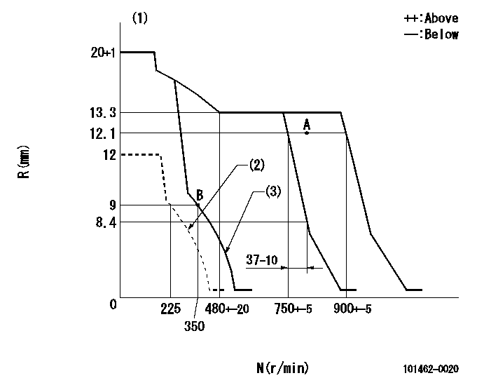
N:Pump speed
R:Rack position (mm)
(1)Target notch: K
(2)Set idle sub-spring
(3)Main spring setting
----------
K=12
----------
----------
K=12
----------
Speed control lever angle
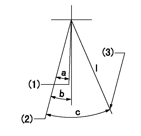
I:Idle
(1)Pump speed = aa
(2)Pump speed = bb (at delivery)
(3)Stopper bolt setting
----------
aa=750r/min bb=900r/min
----------
a=6deg+-5deg b=7deg+-5deg c=27deg+-5deg
----------
aa=750r/min bb=900r/min
----------
a=6deg+-5deg b=7deg+-5deg c=27deg+-5deg
Stop lever angle
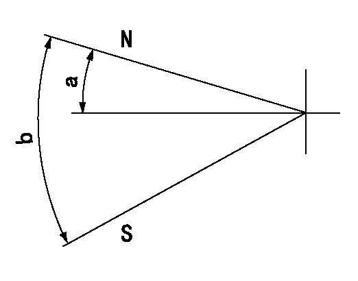
N:Pump normal
S:Stop the pump.
----------
----------
a=4.5deg+-5deg b=53deg+-5deg
----------
----------
a=4.5deg+-5deg b=53deg+-5deg
Timing setting

(1)Pump vertical direction
(2)Position of gear mark 'CC' at No 1 cylinder's beginning of injection
(3)B.T.D.C.: aa
(4)-
----------
aa=15deg
----------
a=(100deg)
----------
aa=15deg
----------
a=(100deg)
Information:
Use the following procedure to update the fuel lines group with the new hose assemblies.Note: Follow all the safety precautions before carrying out any work on the machine.Installation of 488-9360 Hose As between Fuel Tank and Primary filter group
Illustration 1 g06107286
View of inner side of left-hand frame
(A) Fuel tank
(1) 488-9360 Hose As
(2) 383-6118 Clip
Remove former 236-5242 Hose As from fuel tank (A) along the left-hand inner frame and replace with 488-9360 Hose As (1). Use two 383-6118 Clips (2) to mount 488-9360 Hose As (1) to the inner frame.
Illustration 2 g06107793
View of hose routing above the steering box assembly
(1) 488-9360 Hose As
(3) 6D-4244 Clip
Continue routing 488-9360 Hose As (1) above the steering box assembly from left to right using two 6D-4244 Clips (3) in place of the former 1S-0994 Clips.
Illustration 3 g06107808
View of hose routing to the primary filter group
(1) 488-9360 Hose As
(3) 6D-4244 Clips
Route 488-9360 Hose As (1) along the frame and up toward the primary filter group using 6D-4244 Clips (3) to secure to the frame.
Illustration 4 g06108256
View of primary filter group location inner side of right-hand frame
(B) Former fitting
(C) Primary filter group
(1) 488-9360 Hose As
(4) 148-8354 Elbow As
If not previously completed, remove former hose (B) along with the related fitting from the connection on primary filter group (C).
Connect 148-8354 Elbow As (4) onto primary filter group (C) where fitting (B) was removed.
Attach 488-9360 Hose As (1) to 148-8354 Elbow As (4).Installation of 488-9362 Hose As Between Fuel Tank and Fuel Return Manifold
Illustration 5 g06108268
View of left inner frame
(D) Former hose 240-8598 Hose As
Remove former return hose assembly (D) from between the fuel tank and the fuel manifold in the engine.Note: Unless specified otherwise, retain all mounting hardware for reuse.
Illustration 6 g06108327
View of new hose route.
(A) Fuel tank
(2) 383-6118 Clip
(5) 488-9362 Hose As
Connect 488-9362 Hose As (5) to fuel tank where the old hose was removed.
Route 488-9362 Hose As (5) back along the left-hand inner frame towards the engine and use two 383-6118 Clips (2) installed previously to secure hose assembly (5) in place.
Illustration 7 g06112935
View of the rear of the engine
(5) 488-9362 Hose As
(6) 9M-8406 Clip
(7) 329-1681 Clip
Finish installing 488-9362 Hose As (5) by routing hose (5) up the rear side of the engine and connecting the hose where former hose (D) was removed.
Secure 488-9362 Hose As (5) using one 9M-8406 Clip (6) and one 329-1681 Clip (7).Installation of 488-9361 Hose As Between Primary Filter Group and Engine
Illustration 8 g06108399
Top view of the engine underneath the hood
(3) 6D-4244 Clip
(8) 488-9361 Hose As
Remove the existing hose assembly between the primary filter group and the engine.
Install 488-9361 Hose As (8) where the former hose was removed.
Use one 6D-4244 Clip (3) to secure hose assembly (8) to the top of the engine.
Have questions with 101462-0020?
Group cross 101462-0020 ZEXEL
Isuzu
101462-0020
9 400 614 189
5156013430
INJECTION-PUMP ASSEMBLY
4BA1
4BA1
