Information injection-pump assembly
ZEXEL
101461-0470
1014610470
ISUZU
5156014400
5156014400

Rating:
Cross reference number
ZEXEL
101461-0470
1014610470
ISUZU
5156014400
5156014400
Zexel num
Bosch num
Firm num
Name
Calibration Data:
Adjustment conditions
Test oil
1404 Test oil ISO4113 or {SAEJ967d}
1404 Test oil ISO4113 or {SAEJ967d}
Test oil temperature
degC
40
40
45
Nozzle and nozzle holder
105780-8140
Bosch type code
EF8511/9A
Nozzle
105780-0000
Bosch type code
DN12SD12T
Nozzle holder
105780-2080
Bosch type code
EF8511/9
Opening pressure
MPa
17.2
Opening pressure
kgf/cm2
175
Injection pipe
Outer diameter - inner diameter - length (mm) mm 6-2-600
Outer diameter - inner diameter - length (mm) mm 6-2-600
Tester oil delivery pressure
kPa
157
157
157
Tester oil delivery pressure
kgf/cm2
1.6
1.6
1.6
Direction of rotation (viewed from drive side)
Right R
Right R
Injection timing adjustment
Direction of rotation (viewed from drive side)
Right R
Right R
Injection order
1-3-4-2
Pre-stroke
mm
1.95
1.9
2
Beginning of injection position
Drive side NO.1
Drive side NO.1
Difference between angles 1
Cal 1-3 deg. 90 89.5 90.5
Cal 1-3 deg. 90 89.5 90.5
Difference between angles 2
Cal 1-4 deg. 180 179.5 180.5
Cal 1-4 deg. 180 179.5 180.5
Difference between angles 3
Cyl.1-2 deg. 270 269.5 270.5
Cyl.1-2 deg. 270 269.5 270.5
Injection quantity adjustment
Adjusting point
-
Rack position
11.1
Pump speed
r/min
1750
1750
1750
Average injection quantity
mm3/st.
45.8
44.3
47.3
Max. variation between cylinders
%
0
-2.5
2.5
Basic
*
Fixing the rack
*
Injection quantity adjustment_02
Adjusting point
-
Rack position
8.9+-0.5
Pump speed
r/min
300
300
300
Average injection quantity
mm3/st.
8.5
7.1
9.9
Max. variation between cylinders
%
0
-14
14
Fixing the rack
*
Injection quantity adjustment_03
Adjusting point
-
Rack position
16.5++
Pump speed
r/min
150
150
150
Average injection quantity
mm3/st.
75
75
Fixing the lever
*
Remarks
Excess fuel for starting.
Excess fuel for starting.
Timer adjustment
Pump speed
r/min
800
Advance angle
deg.
0.5
Timer adjustment_02
Pump speed
r/min
1000
Advance angle
deg.
1
Timer adjustment_03
Pump speed
r/min
1400
Advance angle
deg.
3
2.5
3.5
Timer adjustment_04
Pump speed
r/min
1750
Advance angle
deg.
5
5
6
Remarks
Finish
Finish
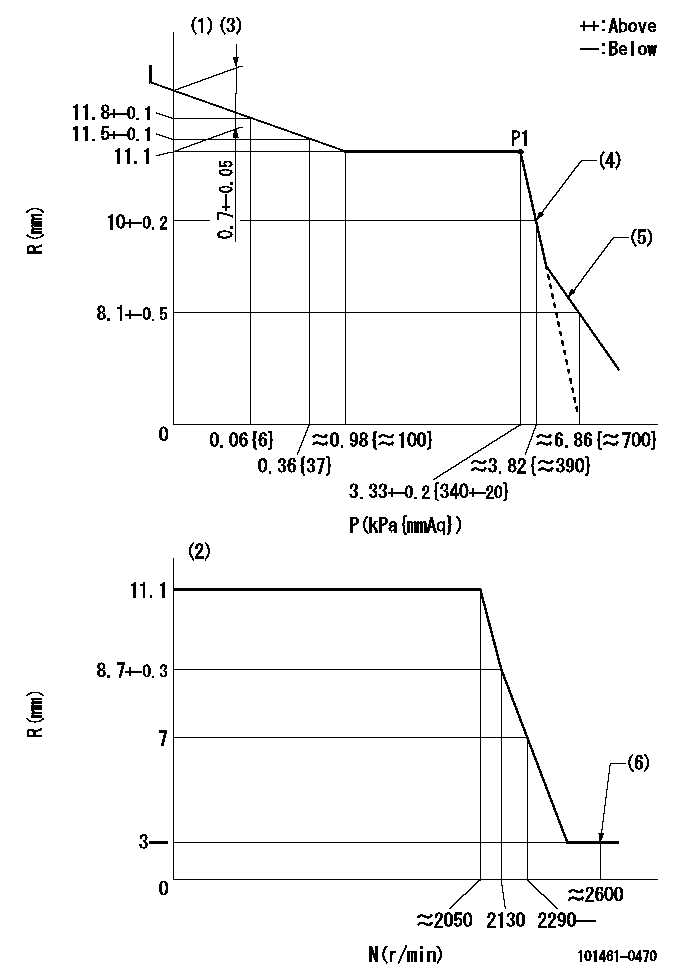
Test data Ex:
Governor adjustment

N:Pump speed
R:Rack position (mm)
P:Negative pressure
(1)Pneumatic governor
(2)Mechanical governor
(3)Acting negative pressure: P1
(4)Adjust at pump speed N1.
(5)Beginning of idle sub spring operation: L1
(6)Injection quantity Q = Q1 or less
----------
N1=500r/min L1=9.1+-0.5mm Q1=3mm3/st
----------
----------
N1=500r/min L1=9.1+-0.5mm Q1=3mm3/st
----------
Timing setting

(1)Pump vertical direction
(2)Position of gear mark 'CC' at No 1 cylinder's beginning of injection
(3)B.T.D.C.: aa
(4)-
----------
aa=12deg
----------
a=(100deg)
----------
aa=12deg
----------
a=(100deg)
Information:
Introduction
The problem that is identified below does not have a known permanent solution. Until a permanent solution is known, use the solution that is identified below.Problem
Elevated sodium in the oil samples.Solution
If the source of the sodium cannot be isolated via other normal testing of individual components (water pumps, oil coolers, and so on), then complete the following procedure:
Shut down the engine and allow system to cool.
Flip the ground level shutdown switch on the truck front bumper and leave the switch engaged. This action disables the fuel injection.
Verify that the engine will crank but the engine does NOT start.
Pull the last exhaust manifold from each bank of the engine.
Pressurize the truck cooling system, refer to Testing and Adjusting, KENR5397 for additional information.
Hold pressure on the cooling system for no more than 10 minutes for the first test. If the leak is bad, holding the pressure too long could risk hydraulic lock.
Illustration 1 g06059950
While cranking the engine, shine a light up into the exhaust manifolds and look for cylinders that are puffing steam and white smoke.
Verify any leaks by pulling the exhaust thermocouple port from the exhaust runner on that cylinder. Check for signs of moisture/steaming in that exhaust runner.
Repair any leaking injector sleeve by replacing the head.