Information injection-pump assembly
ZEXEL
101452-9150
1014529150
YANMAR
12173751011
12173751011
Rating:
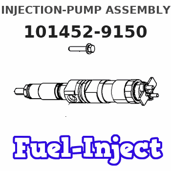
Service parts 101452-9150 INJECTION-PUMP ASSEMBLY:
1.
_
2.
FUEL INJECTION PUMP
5.
AUTOM. ADVANCE MECHANIS
6.
COUPLING PLATE
7.
COUPLING PLATE
8.
_
9.
_
10.
NOZZLE AND HOLDER ASSY
11.
Nozzle and Holder
12.
Open Pre:MPa(Kqf/cm2)
13.
NOZZLE-HOLDER
14.
NOZZLE
15.
NOZZLE SET
Cross reference number
ZEXEL
101452-9150
1014529150
YANMAR
12173751011
12173751011
Zexel num
Bosch num
Firm num
Name
101452-9150
12173751011 YANMAR
INJECTION-PUMP ASSEMBLY
4T90 * K
4T90 * K
Calibration Data:
Adjustment conditions
Test oil
1404 Test oil ISO4113 or {SAEJ967d}
1404 Test oil ISO4113 or {SAEJ967d}
Test oil temperature
degC
40
40
45
Nozzle and nozzle holder
105780-8140
Bosch type code
EF8511/9A
Nozzle
105780-0000
Bosch type code
DN12SD12T
Nozzle holder
105780-2080
Bosch type code
EF8511/9
Opening pressure
MPa
17.2
Opening pressure
kgf/cm2
175
Injection pipe
Outer diameter - inner diameter - length (mm) mm 6-2-600
Outer diameter - inner diameter - length (mm) mm 6-2-600
Tester oil delivery pressure
kPa
157
157
157
Tester oil delivery pressure
kgf/cm2
1.6
1.6
1.6
Direction of rotation (viewed from drive side)
Right R
Right R
Injection timing adjustment
Direction of rotation (viewed from drive side)
Right R
Right R
Injection order
1-3-4-2
Pre-stroke
mm
1.95
1.9
2
Rack position
R=R2
Beginning of injection position
Drive side NO.1
Drive side NO.1
Difference between angles 1
Cal 1-3 deg. 90 89.5 90.5
Cal 1-3 deg. 90 89.5 90.5
Difference between angles 2
Cal 1-4 deg. 180 179.5 180.5
Cal 1-4 deg. 180 179.5 180.5
Difference between angles 3
Cyl.1-2 deg. 270 269.5 270.5
Cyl.1-2 deg. 270 269.5 270.5
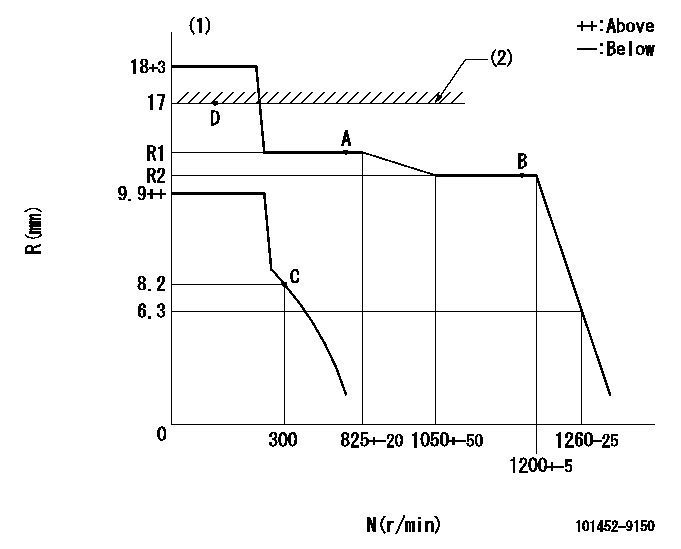
Injection quantity adjustment
Adjusting point
A
Rack position
R1
Pump speed
r/min
800
800
800
Each cylinder's injection qty
mm3/st.
38
36.5
39.5
Fixing the rack
*
Remarks
Measure rack position.
Measure rack position.
Injection quantity adjustment_02
Adjusting point
B
Rack position
R2
Pump speed
r/min
1200
1200
1200
Each cylinder's injection qty
mm3/st.
33.5
32.5
34.5
Basic
*
Fixing the rack
*
Remarks
Measure rack position.
Measure rack position.
Injection quantity adjustment_03
Adjusting point
C
Rack position
8.2
Pump speed
r/min
300
300
300
Each cylinder's injection qty
mm3/st.
10
9
11
Fixing the rack
*
Injection quantity adjustment_04
Adjusting point
D
Rack position
17
Pump speed
r/min
100
100
100
Each cylinder's injection qty
mm3/st.
55
55
60
Fixing the rack
*
Test data Ex:
Governor adjustment
N:Pump speed
R:Rack position (mm)
(1)Target notch: K
(2)RACK LIMIT
----------
K=5
----------
----------
K=5
----------
Speed control lever angle
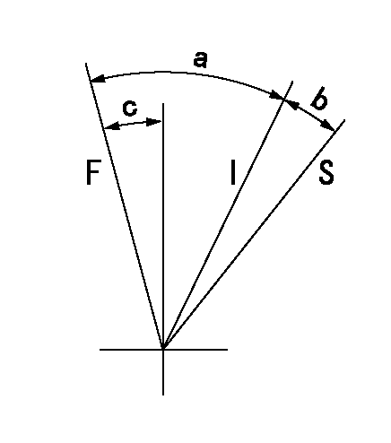
F:Full speed
I:Idle
S:Stop
----------
----------
a=31.5deg+-5deg b=9deg+-3deg c=10deg+-5deg
----------
----------
a=31.5deg+-5deg b=9deg+-3deg c=10deg+-5deg
Information:
Illustration 2 g01681836
(3) CGI flex pipe
Inspect the CGI flex pipe that is installed on all Kenworth and Peterbilt chassis. Check for a previous update to the CGI flex pipe under either a Peterbilt or Kenworth Technical Information BulletinThis work should be charged to your local OEM dealer with instructions that are provided with the service letter.
Peterbilt -Field Repair Notice 408-1 or newer Clean Gas Induction (CGI) and Main Exhaust Pipe Couplings
Kenworth – Technical Information Bulletin Number 43-12 or newer
Drain and save the coolant. The saved coolant can then be reused. Draining the coolant is necessary in order to replace the ARD combustion head.
Illustration 3 g01678253
(4) CGI coolant hose and clamps that are replaced on S/N:SDP1-17026
Inspect the CGI coolant hose and clamps and replace the CGI coolant hose and clamps if it is necessary on S/N:SDP1-17026.
Only replace the hose if the hose has not already been updated. Only black colored hoses should be replaced. The replacement hose is blue or green in color. The blue or green hose does not need to be replaced.Note: There will be some coolant that is left in the line after draining.
Illustration 4 g01678273
(5) Location of fuel control valves
Replace the Pilot and Main Fuel Control Valves. The fuel control valve must not be overtorqued.Torque for the two solenoid valve groups ... 50 5 N m (37 4 lb ft)Final installation torque for the two solenoid nuts ... 20 3 N m (15 2 lb ft)
Replace the ARD combustion head and the components of the ARD utilizing the Disassembly and Assembly Manual, RENR9706 for the proper procedure.Note: Do not install the fuel lines to the ARD Combustion head at this time. These lines will be installed after flushing the fuel system. Leave the protective shipping caps in the fuel ports of the ARD combustion head.
Illustration 5 g01681795
(8) ARD flame detection temperature sensor
In addition to the replacement of the ARD combustion head, install a new ARD flame detection temperature sensor. Refer to Special Instruction, REHS3794 for proper wire routing. If a stainless steel zip tie is removed a newstainless steel zip tie should be used.
Illustration 6 g01681813
(9) CGI temperature sensor
Replace the CGI temperature sensor. Refer to the Disassembly and Assembly Manual, RENR9706 and Disassembly and Assembly Manual, RENR9705 for the proper procedures. Proper wire routing should be followed. If a stainless steel zip tie is removed a new stainless steel zip tie should be used.
Refill the cooling system with the coolant that was saved in Step 8.
Flush the ARD fuel system. Refer to Special Instruction, REHS3848 for the correct procedure.
Flash the engine with the latest software. The release date of the software must be November 2008 or a newer date.Tables that are used in order to look up software and the process for obtaining the software are provided below.
Perform a verification test of the air system and save the file.Note: Refer to Troubleshooting Guide, RENR9343, "Air System Verification Test" that is located on the Service Information System for the pass or fail criteria.
Perform a stationary regeneration. Check
Have questions with 101452-9150?
Group cross 101452-9150 ZEXEL
Yanmar
101452-9150
12173751011
INJECTION-PUMP ASSEMBLY
4T90
4T90