Information injection-pump assembly
BOSCH
9 400 614 183
9400614183
ZEXEL
101452-3131
1014523131
KOMATSU
6202721211
6202721211
Rating:
Service parts 101452-3131 INJECTION-PUMP ASSEMBLY:
1.
_
5.
AUTOM. ADVANCE MECHANIS
6.
COUPLING PLATE
7.
COUPLING PLATE
8.
_
9.
_
11.
Nozzle and Holder
6202-12-3100
12.
Open Pre:MPa(Kqf/cm2)
11.8{120}

15.
NOZZLE SET
Cross reference number
BOSCH
9 400 614 183
9400614183
ZEXEL
101452-3131
1014523131
KOMATSU
6202721211
6202721211
Zexel num
Bosch num
Firm num
Name
101452-3131
9 400 614 183
6202721211 KOMATSU
INJECTION-PUMP ASSEMBLY
4D95S * K 14BC INJECTION PUMP ASSY PE4A,5A, PE
4D95S * K 14BC INJECTION PUMP ASSY PE4A,5A, PE
Calibration Data:
Adjustment conditions
Test oil
1404 Test oil ISO4113 or {SAEJ967d}
1404 Test oil ISO4113 or {SAEJ967d}
Test oil temperature
degC
40
40
45
Nozzle and nozzle holder
105780-8140
Bosch type code
EF8511/9A
Nozzle
105780-0000
Bosch type code
DN12SD12T
Nozzle holder
105780-2080
Bosch type code
EF8511/9
Opening pressure
MPa
17.2
Opening pressure
kgf/cm2
175
Injection pipe
Outer diameter - inner diameter - length (mm) mm 6-2-600
Outer diameter - inner diameter - length (mm) mm 6-2-600
Overflow valve
131424-7420
Overflow valve opening pressure
kPa
255
221
289
Overflow valve opening pressure
kgf/cm2
2.6
2.25
2.95
Tester oil delivery pressure
kPa
157
157
157
Tester oil delivery pressure
kgf/cm2
1.6
1.6
1.6
Direction of rotation (viewed from drive side)
Right R
Right R
Injection timing adjustment
Direction of rotation (viewed from drive side)
Right R
Right R
Injection order
1-2-4-3
Pre-stroke
mm
1.5
1.45
1.55
Beginning of injection position
Drive side NO.1
Drive side NO.1
Difference between angles 1
Cyl.1-2 deg. 90 89.5 90.5
Cyl.1-2 deg. 90 89.5 90.5
Difference between angles 2
Cal 1-4 deg. 180 179.5 180.5
Cal 1-4 deg. 180 179.5 180.5
Difference between angles 3
Cal 1-3 deg. 270 269.5 270.5
Cal 1-3 deg. 270 269.5 270.5
Injection quantity adjustment
Adjusting point
A
Rack position
11
Pump speed
r/min
1225
1225
1225
Average injection quantity
mm3/st.
33.4
32.4
34.4
Max. variation between cylinders
%
0
-2.5
2.5
Basic
*
Fixing the lever
*
Injection quantity adjustment_02
Adjusting point
-
Rack position
9.5+-0.5
Pump speed
r/min
410
410
410
Average injection quantity
mm3/st.
8
7
9
Max. variation between cylinders
%
0
-15
15
Fixing the rack
*
Remarks
Adjust only variation between cylinders; adjust governor according to governor specifications.
Adjust only variation between cylinders; adjust governor according to governor specifications.
Test data Ex:
Governor adjustment
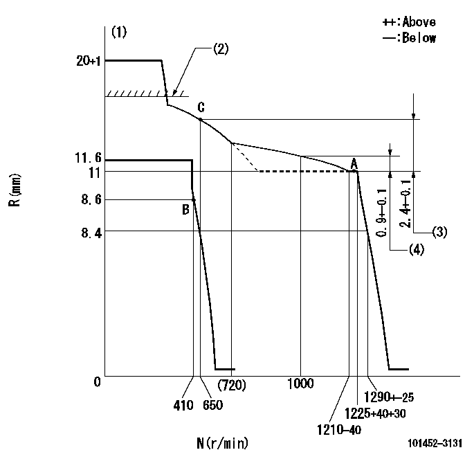
N:Pump speed
R:Rack position (mm)
(1)Target notch: K
(2)RACK LIMIT: RAL
(3)Rack difference between N = N1 and N = N2
(4)Rack difference between N = N3 and N = N4
----------
K=7 RAL=15+0.2mm N1=1225r/min N2=650r/min N3=1225r/min N4=1000r/min
----------
----------
K=7 RAL=15+0.2mm N1=1225r/min N2=650r/min N3=1225r/min N4=1000r/min
----------
Speed control lever angle
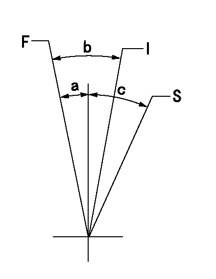
F:Full speed
I:Idle
S:Stop
----------
----------
a=3deg+-5deg b=27deg+-5deg c=32deg+-3deg
----------
----------
a=3deg+-5deg b=27deg+-5deg c=32deg+-3deg
Timing setting

(1)Pump vertical direction
(2)Position of key groove at No 1 cylinder's beginning of injection
(3)Stamp aligning marks on the pump housing flange.
(4)-
----------
----------
a=46deg18min+-3deg b=13deg42min+-30min
----------
----------
a=46deg18min+-3deg b=13deg42min+-30min
Information:
Mast Cab Side Bank-Lube Points and Locations
Illustration 14 g06355954
Mast cab side bank-lube points
(A) Right Mast Pivot Pin
(B) Right Mast Raise Cylinder Upper Pin
(C) Gear Box Air Seal (Top side)
(D) Gear Box Top Lip Seal Top Air Seal (Bottom Side)
(E) Pipe Rack Upper Swing Cylinder Head End
(F) Pipe Rack Carousel Support Bearing
(G) Pipe Rack Journal Bearing
(H) Pipe Rack Journal Bearing
(J) Left Side Top Sheave Pin
(K) Right Side Top Sheave Pin
(L) Left Side Bottom Sheave Pin
(M) Right Side Bottom Sheave Pin
(N) Right Side Pipe Positioner Roller Pin
(P) Right Side Pipe Positioner Swing Pin
(R) Left Side Pipe Positioner Swing Pin
(S) Left Side Pipe Positioner Roller Pin
Table 12
Mast Cab Side Bank
Item Description Sleeve color
A Right Mast Pivot Pin Red
B Right Mast Raise Cylinder Upper Pin Red
C Gear Box Air Seal (Top side) Nut
D Gear Box Top Lip Seal Top Air Seal (Bottom Side) Red
E Pipe Rack Upper Swing Cylinder Head End Red
F Pipe Rack Carousel Support Bearing Red
G Pipe Rack Journal Bearing Red
H Pipe Rack Journal Bearing Red
J Left Side Top Sheave Pin Red
K Right Side Top Sheave Pin Red
L Left Side Bottom Sheave Pin Red
M Right Side Bottom Sheave Pin Red
N Right Side Pipe Positioner Roller Pin Red
P Right Side Pipe Positioner Swing Pin Nut
R Left Side Pipe Positioner Swing Pin Nut
S Right Side Pipe Positioner Roller Pin Red Hydraulic Break Out Wrenches (Hobo)-Lube Points
Illustration 15 g06355971
Hobo-lube points
(A) HOBO Rotate Cylinder Head End
(B) HOBO Swing Pivot Pin Top
(C) HOBO Swing Pivot Pin Bottom
(D) HOBO Swing Cylinder Rod End
(E) HOBO Clamp Slide
(F) HOBO Rotate Cylinder Rod End
(G) HOBO Clamp Cylinder Rod End
(H) HOBO Clamp Pin
Table 13
Hydraulic Break Out Wrenches (HOBO)
Item Description Sleeve color
A HOBO Rotate Cylinder Head End Nut
B HOBO Swing Pivot Pin Top Red
C HOBO Swing Pivot Pin Bottom Red
D HOBO Swing Cylinder Rod End Red
E HOBO Clamp Slide Red
F HOBO Rotate Cylinder Rod End Nut
G HOBO Clamp Cylinder Rod End Nut
H HOBO Clamp Pin Red
Have questions with 101452-3131?
Group cross 101452-3131 ZEXEL
Komatsu
Komatsu
Komatsu
Komatsu
101452-3131
9 400 614 183
6202721211
INJECTION-PUMP ASSEMBLY
4D95S
4D95S