Information injection-pump assembly
BOSCH
9 400 614 182
9400614182
ZEXEL
101452-3123
1014523123
KOMATSU
6204721422
6204721422
Rating:
Service parts 101452-3123 INJECTION-PUMP ASSEMBLY:
1.
_
5.
AUTOM. ADVANCE MECHANIS
6.
COUPLING PLATE
7.
COUPLING PLATE
8.
_
9.
_
11.
Nozzle and Holder
6202-12-3100
12.
Open Pre:MPa(Kqf/cm2)
11.8{120}

15.
NOZZLE SET
Cross reference number
BOSCH
9 400 614 182
9400614182
ZEXEL
101452-3123
1014523123
KOMATSU
6204721422
6204721422
Zexel num
Bosch num
Firm num
Name
101452-3123
9 400 614 182
6204721422 KOMATSU
INJECTION-PUMP ASSEMBLY
4D95L K 14BC INJECTION PUMP ASSY PE4A,5A, PE
4D95L K 14BC INJECTION PUMP ASSY PE4A,5A, PE
Calibration Data:
Adjustment conditions
Test oil
1404 Test oil ISO4113 or {SAEF967d}
1404 Test oil ISO4113 or {SAEF967d}
Test oil temperature
degC
40
40
45
Nozzle and nozzle holder
105780-8140
Bosch type code
EF8511/9A
Nozzle
105780-0000
Bosch type code
DN12SD12T
Nozzle holder
105780-2080
Bosch type code
EF8511/9
Opening pressure
MPa
17.2
Opening pressure
kgf/cm2
175
Injection pipe
Outer diameter - inner diameter - length (mm) mm 6-2-600
Outer diameter - inner diameter - length (mm) mm 6-2-600
Tester oil delivery pressure
kPa
157
157
157
Tester oil delivery pressure
kgf/cm2
1.6
1.6
1.6
Direction of rotation (viewed from drive side)
Right R
Right R
Injection timing adjustment
Direction of rotation (viewed from drive side)
Right R
Right R
Injection order
1-2-4-3
Pre-stroke
mm
1.5
1.45
1.55
Beginning of injection position
Drive side NO.1
Drive side NO.1
Difference between angles 1
Cyl.1-2 deg. 90 89.5 90.5
Cyl.1-2 deg. 90 89.5 90.5
Difference between angles 2
Cal 1-4 deg. 180 179.5 180.5
Cal 1-4 deg. 180 179.5 180.5
Difference between angles 3
Cal 1-3 deg. 270 269.5 270.5
Cal 1-3 deg. 270 269.5 270.5
Injection quantity adjustment
Adjusting point
A
Rack position
12
Pump speed
r/min
900
900
900
Average injection quantity
mm3/st.
45.8
44.8
46.8
Max. variation between cylinders
%
0
-2.5
2.5
Basic
*
Fixing the lever
*
Injection quantity adjustment_02
Adjusting point
-
Rack position
8.3+-0.5
Pump speed
r/min
400
400
400
Average injection quantity
mm3/st.
11
10
12
Max. variation between cylinders
%
0
-15
15
Fixing the rack
*
Remarks
Adjust only variation between cylinders; adjust governor according to governor specifications.
Adjust only variation between cylinders; adjust governor according to governor specifications.
Test data Ex:
Governor adjustment
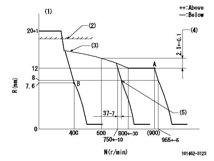
N:Pump speed
R:Rack position (mm)
(1)Target notch: K
(2)RACK CAP: R1
(3)The torque control spring must does not have a set force.
(4)Rack difference between N = N1 and N = N2
(5)Idle sub spring setting: L1.
----------
K=10 R1=(17.5)mm N1=900r/min N2=500r/min L1=8-0.5mm
----------
----------
K=10 R1=(17.5)mm N1=900r/min N2=500r/min L1=8-0.5mm
----------
Speed control lever angle
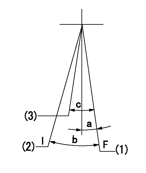
F:Full speed
I:Idle
(1)Set the speed at aa, set the stopper bolt
(2)Stopper bolt setting
(3)Set the pump speed at bb.
----------
aa=955r/min bb=750r/min
----------
a=(1deg)+-5deg b=(23deg)+-5deg c=(6deg)+-5deg
----------
aa=955r/min bb=750r/min
----------
a=(1deg)+-5deg b=(23deg)+-5deg c=(6deg)+-5deg
Stop lever angle
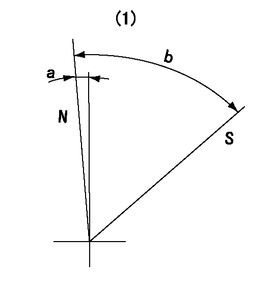
N:Pump normal
S:Stop the pump.
(1)No return spring
----------
----------
a=4deg+-5deg b=53deg+-5deg
----------
----------
a=4deg+-5deg b=53deg+-5deg
Timing setting

(1)Pump vertical direction
(2)Position of key groove at No 1 cylinder's beginning of injection
(3)Stamp aligning marks on the pump housing flange.
(4)-
----------
----------
a=46deg18min+-3deg b=13deg42min+-30min
----------
----------
a=46deg18min+-3deg b=13deg42min+-30min
Information:
Introduction
Do not perform any procedure in this Special Instruction until you read this information and you understand this information.Affected Engines
This Special Instruction provides the proper instructions on accessing the timing hole for high pressure fuel pumps on C7 Engines. The procedure is for the C7 Engines that are in General Motors and Blue Bird chassis. The timing hole may need to be accessed after the high pressure fuel injection pump is replaced in order to time the new high pressure pump.Disassembly Procedure
Illustration 1 g01458243
(1) Clean Gas Induction (CGI) Cooler (2) Aftertreatment Regeneration Device (ARD) Housing Bracket (3) Timing Hole Plug (4) Aftertreatment Regeneration Device (ARD) Housing
Illustration 2 g01458244
(5) Mounting bolts for the bracket for the ARD housing
Remove the two mounting bolts (5) from the bracket for the housing for the ARD. Use a 18 millimeter socket in order to loosen the mounting bolts. Make sure that the socket can flex. Also use a 12 inch socket extension in order to loosen the mounting bolts. After the bolts have been broken loose the bolts must be turned by hand in order to finish removing the bolts.
Illustration 3 g01458245
(6) Exhaust clamp for the ARD
Loosen the exhaust clamp (6) for the ARD. Slide the exhaust clamp down the exhaust pipe. Do not remove the clamp completely. This may cause the clamp to become bent. This may cause the clamp to not fit properly.
Illustration 4 g01458247
(7) Timing hole for the high pressure fuel pump
Move the housing bracket for the ARD to the side. This will provide enough clearance in order to remove the plug from the timing hole.The timing hole can be used to check the timing for the fuel injection pump. If the fuel injection pump needs to be timed properly then refer to Disassembly and Assembly, RENR9707, "Fuel Injection Pump - Install" for the proper installation procedure to ensure the the fuel injection pump will be timed properly.Assembly Procedure
Illustration 5 g01458476
(3) Timing hole plug
Reinstall the timing hole plug (3) back into the timing hole.
Illustration 6 g01458245
(6) Exhaust clamp for the ARD
Reinstall the exhaust clamp (6) for the ARD.
Illustration 7 g01458244
(5) Mounting bolts for the housing bracket for the ARD
Move the bracket for the ARD into the original position. Reinstall the mounting bolts (5) for the mounting bracket for the ARD.
Have questions with 101452-3123?
Group cross 101452-3123 ZEXEL
Komatsu
Komatsu
Komatsu
101452-3123
9 400 614 182
6204721422
INJECTION-PUMP ASSEMBLY
4D95L
4D95L