Information injection-pump assembly
ZEXEL
101452-3070
1014523070

Rating:
Cross reference number
ZEXEL
101452-3070
1014523070
Zexel num
Bosch num
Firm num
Name
Calibration Data:
Adjustment conditions
Test oil
1404 Test oil ISO4113 or {SAEJ967d}
1404 Test oil ISO4113 or {SAEJ967d}
Test oil temperature
degC
40
40
45
Nozzle and nozzle holder
105780-8140
Bosch type code
EF8511/9A
Nozzle
105780-0000
Bosch type code
DN12SD12T
Nozzle holder
105780-2080
Bosch type code
EF8511/9
Opening pressure
MPa
17.2
Opening pressure
kgf/cm2
175
Injection pipe
Outer diameter - inner diameter - length (mm) mm 6-2-600
Outer diameter - inner diameter - length (mm) mm 6-2-600
Overflow valve opening pressure
kPa
157
123
191
Overflow valve opening pressure
kgf/cm2
1.6
1.25
1.95
Tester oil delivery pressure
kPa
157
157
157
Tester oil delivery pressure
kgf/cm2
1.6
1.6
1.6
Direction of rotation (viewed from drive side)
Right R
Right R
Injection timing adjustment
Direction of rotation (viewed from drive side)
Right R
Right R
Injection order
1-2-4-3
Pre-stroke
mm
1.5
1.45
1.55
Rack position
Point A R=A
Point A R=A
Beginning of injection position
Drive side NO.1
Drive side NO.1
Difference between angles 1
Cyl.1-2 deg. 90 89.5 90.5
Cyl.1-2 deg. 90 89.5 90.5
Difference between angles 2
Cal 1-4 deg. 180 179.5 180.5
Cal 1-4 deg. 180 179.5 180.5
Difference between angles 3
Cal 1-3 deg. 270 269.5 270.5
Cal 1-3 deg. 270 269.5 270.5
Injection quantity adjustment
Adjusting point
A
Rack position
11.3
Pump speed
r/min
1225
1225
1225
Average injection quantity
mm3/st.
34.6
33.6
35.6
Max. variation between cylinders
%
0
-2.5
2.5
Basic
*
Fixing the lever
*
Injection quantity adjustment_02
Adjusting point
-
Rack position
9.3+-0.5
Pump speed
r/min
410
410
410
Average injection quantity
mm3/st.
8
7
9
Max. variation between cylinders
%
0
-15
15
Fixing the rack
*
Remarks
Adjust only variation between cylinders; adjust governor according to governor specifications.
Adjust only variation between cylinders; adjust governor according to governor specifications.
Test data Ex:
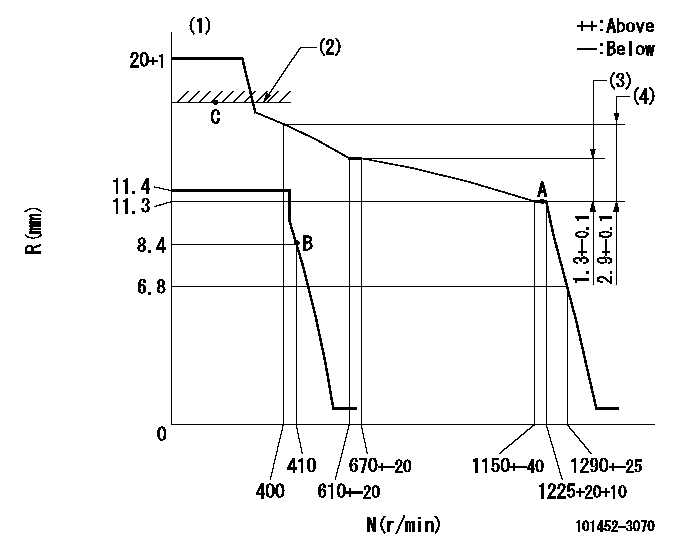
Governor adjustment

N:Pump speed
R:Rack position (mm)
(1)Target notch: K
(2)RACK CAP: R1
(3)Rack difference between N = N1 and N = N2
(4)Rack difference between N = N3 and N = N4
----------
K=7 R1=(17.5)mm N1=1225r/min N2=650r/min N3=1225r/min N4=400r/min
----------
----------
K=7 R1=(17.5)mm N1=1225r/min N2=650r/min N3=1225r/min N4=400r/min
----------
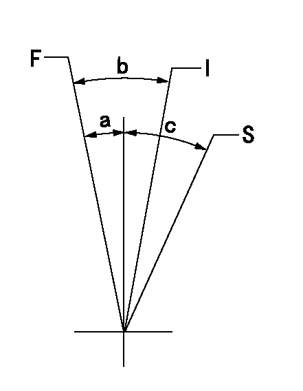
Speed control lever angle

F:Full speed
I:Idle
S:Stop
----------
----------
a=2deg+-5deg b=25deg+-5deg c=32deg+-3deg
----------
----------
a=2deg+-5deg b=25deg+-5deg c=32deg+-3deg
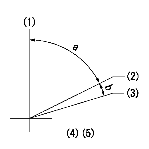
Timing setting

(1)Pump vertical direction
(2)Position of key groove at No 1 cylinder's beginning of injection
(3)Stamp aligning marks on the pump housing flange.
(4)-
----------
----------
a=46deg18min+-3deg b=13deg42min+-30min
----------
----------
a=46deg18min+-3deg b=13deg42min+-30min
Information:
Introduction
The problem that is identified in the technical information bulletin that follows does not have a known permanent solution. Until a permanent solution is known, use the solution that is identified below.Problem
In order to extend the life of fuel injectors on the above listed engines, the injector solenoids need to remain cool.Solution
Illustration 1 g01404067
Hole in exhaust rocker arm for oil sprayThe system was developed in order to provide a stream of engine oil to the injector solenoids. The design uses the existing oil supply from the valve mechanism. The oil spray is directed out of the exhaust rocker arms. There is one 0.7 mm (0.028 inch) hole (1) in each exhaust rocker arm.Note: When you are servicing the valve mechanism, the oil ports must remain free of debris.
Illustration 2 g01404069
(2) Location of oil spray