Information injection-pump assembly
ZEXEL
101452-3030
1014523030
KOMATSU
6204721410
6204721410
Rating:
Service parts 101452-3030 INJECTION-PUMP ASSEMBLY:
1.
_
5.
AUTOM. ADVANCE MECHANIS
6.
COUPLING PLATE
7.
COUPLING PLATE
8.
_
9.
_
11.
Nozzle and Holder
12.
Open Pre:MPa(Kqf/cm2)
11.8(120)
15.
NOZZLE SET
Cross reference number
ZEXEL
101452-3030
1014523030
KOMATSU
6204721410
6204721410
Zexel num
Bosch num
Firm num
Name
Calibration Data:
Adjustment conditions
Test oil
1404 Test oil ISO4113 or {SAEJ967d}
1404 Test oil ISO4113 or {SAEJ967d}
Test oil temperature
degC
40
40
45
Nozzle and nozzle holder
105780-8140
Bosch type code
EF8511/9A
Nozzle
105780-0000
Bosch type code
DN12SD12T
Nozzle holder
105780-2080
Bosch type code
EF8511/9
Opening pressure
MPa
17.2
Opening pressure
kgf/cm2
175
Injection pipe
Outer diameter - inner diameter - length (mm) mm 6-2-600
Outer diameter - inner diameter - length (mm) mm 6-2-600
Tester oil delivery pressure
kPa
157
157
157
Tester oil delivery pressure
kgf/cm2
1.6
1.6
1.6
Direction of rotation (viewed from drive side)
Right R
Right R
Injection timing adjustment
Direction of rotation (viewed from drive side)
Right R
Right R
Injection order
1-2-4-3
Pre-stroke
mm
1.5
1.45
1.55
Beginning of injection position
Drive side NO.1
Drive side NO.1
Difference between angles 1
Cyl.1-2 deg. 90 89.5 90.5
Cyl.1-2 deg. 90 89.5 90.5
Difference between angles 2
Cal 1-4 deg. 180 179.5 180.5
Cal 1-4 deg. 180 179.5 180.5
Difference between angles 3
Cal 1-3 deg. 270 269.5 270.5
Cal 1-3 deg. 270 269.5 270.5
Injection quantity adjustment
Adjusting point
A
Rack position
12
Pump speed
r/min
900
900
900
Average injection quantity
mm3/st.
45.8
44.8
46.8
Max. variation between cylinders
%
0
-2.5
2.5
Basic
*
Fixing the lever
*
Injection quantity adjustment_02
Adjusting point
-
Rack position
8.3+-0.5
Pump speed
r/min
400
400
400
Average injection quantity
mm3/st.
11
10
12
Max. variation between cylinders
%
0
-15
15
Fixing the rack
*
Remarks
Adjust only variation between cylinders; adjust governor according to governor specifications.
Adjust only variation between cylinders; adjust governor according to governor specifications.
Test data Ex:
Governor adjustment
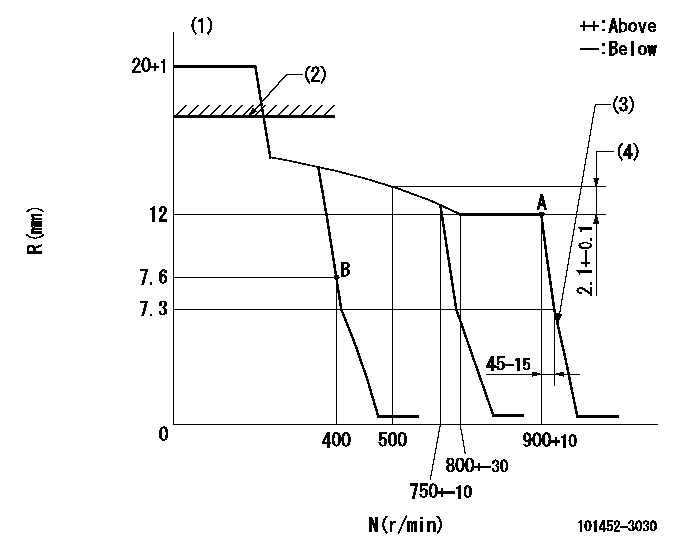
N:Pump speed
R:Rack position (mm)
(1)Target notch: K
(2)RACK CAP: R1
(3)Idle sub spring setting: L1.
(4)Rack difference between N = N1 and N = N2
----------
K=15 R1=(17.5)mm L1=7.3-0.5mm N1=900r/min N2=500r/min
----------
----------
K=15 R1=(17.5)mm L1=7.3-0.5mm N1=900r/min N2=500r/min
----------
Speed control lever angle
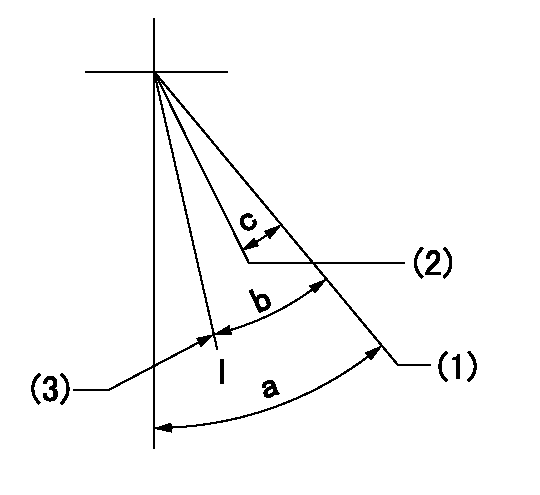
I:Idle
(1)Set the pump speed at aa
(2)Set the pump speed at bb.
(3)Stopper bolt setting
----------
aa=900r/min bb=750r/min
----------
a=47deg+-5deg b=26deg+-5deg c=7deg+-5deg
----------
aa=900r/min bb=750r/min
----------
a=47deg+-5deg b=26deg+-5deg c=7deg+-5deg
Stop lever angle
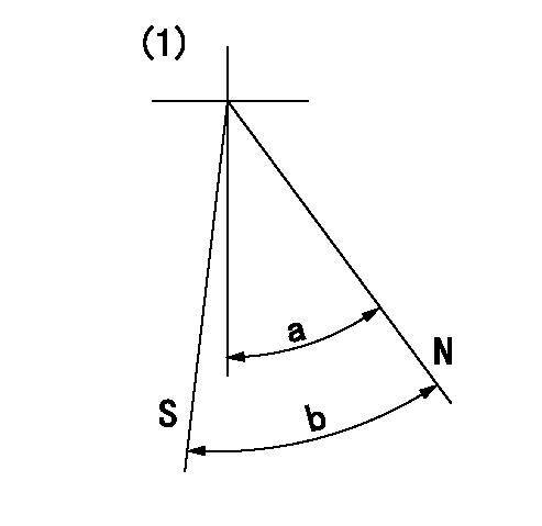
N:Pump normal
S:Stop the pump.
(1)No return spring
----------
----------
a=47deg+-5deg b=53deg+-5deg
----------
----------
a=47deg+-5deg b=53deg+-5deg
Timing setting
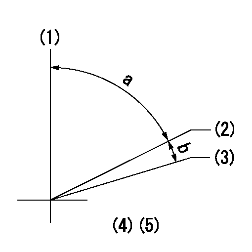
(1)Pump vertical direction
(2)Position of key groove at No 1 cylinder's beginning of injection
(3)Stamp aligning marks on the pump housing flange.
(4)-
(5)-
----------
----------
a=46deg18min+-3deg b=13deg42min+-30min
----------
----------
a=46deg18min+-3deg b=13deg42min+-30min
Information:
Introduction
Do not perform any procedure in this Special Instruction until you read this information and you understand this information.This Special Instruction is intended to provide instructions on installing O-Ring seals on the injector sleeves.Required Parts
Table 1
Required Parts
Part Number Part Name Quantity
227-1200 Injector Sleeve 6
310-7255 O-Ring Seal 6
310-7257 O-Ring Seal 6 Required Tools
Table 2
Required Tools
Part Number Part Name Quantity
221-9777 Sleeve Installer 1
4C-5552 Large Bore Brush 1
4C-9507 Retaining Compound 1 Cleaning the Injector Sleeves and Installing O-Ring Seal
Note: Thoroughly clean the injector sleeves with the 4C-5552 Large Bore Brush .Note: Thoroughly clean the bore in the cylinder head for the injector sleeves with the 4C-5552 Large Bore Brush .Note: Do not apply any lubricant to the O-ring seals.
Illustration 1 g01379557
(1) 310-7255 O-Ring Seal (2) 310-7257 O-Ring Seal (3) 227-1200 Injector Sleeve
Install the upper O-Ring (1) on the injector sleeve (3) .Note: The upper O-Ring is dark blue.
Install the lower O-Ring (2) on the injector sleeve (3) .Note: The lower O-Ring (2) is turquoise.
Position the injector sleeve on the 221-9777 Sleeve Installer .
Apply a thin coat of 4C-9507 Retaining Compound around the outer circumference of area (A). Ensure that the retaining compound does not make contact with the O-Ring seal at any time.
Position the injector sleeve (3) in the cylinder head by using the 221-9777 Sleeve Installer .
Slowly push the injector sleeve into the cylinder head by gently tapping with a hammer.Note: Allow the 4C-9507 Retaining Compound to cure for two hours at 21 °C (70 °F) before filling the engine with coolant. Longer curing time is required for lower temperatures.
Install the unit injectors. Refer to Disassembly and Assembly, "Unit Injector-Install" to install the unit injectors.
