Information injection-pump assembly
BOSCH
F 01G 09U 01M
f01g09u01m
ZEXEL
101451-9590
1014519590

Rating:
Service parts 101451-9590 INJECTION-PUMP ASSEMBLY:
1.
_
6.
COUPLING PLATE
7.
COUPLING PLATE
8.
_
9.
_
11.
Nozzle and Holder
16600-36W00
12.
Open Pre:MPa(Kqf/cm2)
9.8{100}

15.
NOZZLE SET
Cross reference number
BOSCH
F 01G 09U 01M
f01g09u01m
ZEXEL
101451-9590
1014519590
Zexel num
Bosch num
Firm num
Name
Calibration Data:
Adjustment conditions
Test oil
1404 Test oil ISO4113 or {SAEJ967d}
1404 Test oil ISO4113 or {SAEJ967d}
Test oil temperature
degC
40
40
45
Nozzle and nozzle holder
105780-8140
Bosch type code
EF8511/9A
Nozzle
105780-0000
Bosch type code
DN12SD12T
Nozzle holder
105780-2080
Bosch type code
EF8511/9
Opening pressure
MPa
17.2
Opening pressure
kgf/cm2
175
Injection pipe
Outer diameter - inner diameter - length (mm) mm 6-2-600
Outer diameter - inner diameter - length (mm) mm 6-2-600
Tester oil delivery pressure
kPa
157
157
157
Tester oil delivery pressure
kgf/cm2
1.6
1.6
1.6
Direction of rotation (viewed from drive side)
Right R
Right R
Injection timing adjustment
Direction of rotation (viewed from drive side)
Right R
Right R
Injection order
1-3-4-2
Pre-stroke
mm
2
1.95
2.05
Beginning of injection position
Drive side NO.1
Drive side NO.1
Difference between angles 1
Cal 1-3 deg. 90 89.5 90.5
Cal 1-3 deg. 90 89.5 90.5
Difference between angles 2
Cal 1-4 deg. 180 179.5 180.5
Cal 1-4 deg. 180 179.5 180.5
Difference between angles 3
Cyl.1-2 deg. 270 269.5 270.5
Cyl.1-2 deg. 270 269.5 270.5
Injection quantity adjustment
Adjusting point
A
Rack position
12
Pump speed
r/min
1750
1750
1750
Average injection quantity
mm3/st.
61.6
57.6
65.6
Max. variation between cylinders
%
0
-4
4
Fixing the rack
*
Injection quantity adjustment_02
Adjusting point
B
Rack position
12
Pump speed
r/min
1000
1000
1000
Average injection quantity
mm3/st.
55.2
54.2
56.2
Max. variation between cylinders
%
0
-2.5
2.5
Basic
*
Fixing the rack
*
Injection quantity adjustment_03
Adjusting point
C
Rack position
7.4+-0.5
Pump speed
r/min
350
350
350
Average injection quantity
mm3/st.
10
7.7
12.3
Max. variation between cylinders
%
0
-15
15
Fixing the rack
*
Timer adjustment
Pump speed
r/min
300++
Advance angle
deg.
0
0
0
Remarks
Start
Start
Timer adjustment_02
Pump speed
r/min
400
Advance angle
deg.
0.5
Timer adjustment_03
Pump speed
r/min
450
Advance angle
deg.
0.7
Timer adjustment_04
Pump speed
r/min
700
Advance angle
deg.
1
0.5
1.5
Timer adjustment_05
Pump speed
r/min
1500
Advance angle
deg.
5
4.5
5.5
Timer adjustment_06
Pump speed
r/min
1850
Advance angle
deg.
7.5
7
8
Remarks
Finish
Finish
Test data Ex:
Governor adjustment
N:Pump speed
R:Rack position (mm)
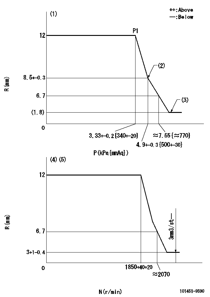
(1)Pneumatic governor
(2)Beginning of idle sub spring operation: L1
(3)With stopper disk.
(4)Mechanical governor
(5)Acting negative pressure: P1
----------
L1=8.5+-0.3mm
----------
----------
L1=8.5+-0.3mm
----------
0000001101
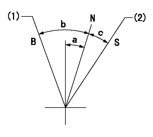
N:Normal
B:When boosted
S:Stop
(1)Rack position = aa
(2)Rack position corresponding to bb
----------
aa=17.5mm bb=(1.8)mm
----------
a=9.5deg+-5deg b=11deg+-5deg c=20.5deg+-3deg
----------
aa=17.5mm bb=(1.8)mm
----------
a=9.5deg+-5deg b=11deg+-5deg c=20.5deg+-3deg
0000001501 ACS
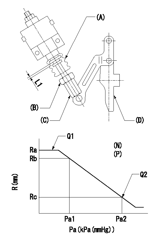
(N): Speed of the pump
(P): governor's negative pressure
(Pa): aneroid compensator's negative pressure
(A) rubber boot
(B) Nut
(c) Nut
(D) Lever
1. Aneroid compensator installation
(1)Turn nut (C) to adjust gap to L1. (Remove rubber boot at adjustment.)
(2)Lock using nut (B).
(3)After installation, the lever D must move smoothly when the lever D is moved to the excess fuel side, and R = R1 or more.
----------
L1=0.1~0.5mm
----------
N=1000r/min P=0.69kPa(70mmAq) Ra=12-0.05mm Rb=11.95mm Rc=11.3+-0.2mm Pa1=8-5.3kPa(60-40mmHg) Pa2=16.7kPa(125mmHg) Q1=- Q2=-
----------
L1=0.1~0.5mm
----------
N=1000r/min P=0.69kPa(70mmAq) Ra=12-0.05mm Rb=11.95mm Rc=11.3+-0.2mm Pa1=8-5.3kPa(60-40mmHg) Pa2=16.7kPa(125mmHg) Q1=- Q2=-
Timing setting

(1)Pump vertical direction
(2)Position of gear mark 'K' at No 1 cylinder's beginning of injection
(3)B.T.D.C.: aa
(4)-
----------
aa=10deg
----------
a=(50deg)
----------
aa=10deg
----------
a=(50deg)
Information:
Reassemble Motor to Pump
Thoroughly clean the motor shaft and the hollow pump shaft. Remove the tape from the key (5) and keyway.
Apply a liberal amount of Loctite Nickel Anti-Seize No. 77164 to the pump shaft.
Install the shaft key (5) into the keyway.
Slide the motor shaft into the hollow pump shaft.
Reinstall the four washers (2) and nuts (1).Primary Strainer Removal and Installation
Primary Strainer Removal
Illustration 34 g06272994
(1) Primary Strainer
(2) Drain Plug
(3) Nut
(4) Strainer Cover
(5) Compression Ring
(6) Seal
(7) Strainer Housing
(8) Strainer Screens
Place a suitable drain pan underneath the primary strainer (1) to capture DEF fluid.
Remove and store the drain plug (2) from the bottom of the strainer cover (4). Allow DEF fluid to drain.
Inspect drain plug (1) and any seals, replace if damaged.
Install drain plug (2) into the bottom of the strainer cover (4).
Remove and store eight nuts (3) and the compression flange (5) located around the bottom of the strainer cover (4).
Remove and store the strainer cover (4) of the primary strainer (1).
Remove and inspect seal (6), replace if damaged.
Remove and discard the primary strainer screens (8) from the screen housing (7).Primary Strainer Installation
Install new primary strainer screens (8) into the screen housing (7).
Install screen housing (7) into the primary strainer (1).
Install the seal (6) onto the bottom of the strainer cover (4).
Install the strainer cover (4), compression flange (5), and eight nuts (3).
Open primary valve, operate DEF Transfer Pump and check for leaks around the bottom of the primary strainer (1).
Remove drain pan and dispose of DEF fluid.Secondary Strainer Removal and Installation
Secondary Strainer Removal
Illustration 35 g06272975
(1) Secondary Strainer
(2) Strainer Element
(3) Seal
(4) Strainer Cover
(5) Bolt
Place a suitable drain pan underneath the secondary strainer (1) to capture DEF fluid.
Remove and store the bolts (5).
Remove and store strainer cover (4).
Remove and inspect seal (3), replace if damaged.
Remove and discard strainer element (2).Secondary Strainer Installation
Install new secondary strainer element (2) into the secondary strainer (1).
Install the seal (3) onto the bottom of the strainer cover (4).
Install the strainer cover (4) with bolts (5).
Open secondary valve, operate DEF Transfer Pump and check for leaks around the bottom of the secondary strainer (1).
Remove drain pan and dispose of DEF fluid.Product Description
Extended Warranties and Service Contracts
A wide variety of protection plans are available for Cat Engines. Consult your Caterpillardealer for detailed information on the specific programs and coverages that are available.DEF Transfer Pump is an optional attachment to an engine system. Refer to the warranty information for your engine or consult your Caterpillar dealer.Customer Assistance
USA and Canada
When a problem arises concerning the operation or the service of a Marine engine, the problem will normally be managed by the dealer in your area.Your satisfaction is a primary concern to Caterpillar and to Caterpillar dealers. If you have a problem that has not been handled to your complete satisfaction, follow these steps:
Discuss your problem with a manager from the dealership.
If your problem cannot be resolved at the dealer level, use the phone number that is listed below to talk with a Field Service Coordinator:877-228-9900
The normal hours are from 7:00 AM