Information injection-pump assembly
ZEXEL
101451-9560
1014519560

Rating:
Cross reference number
ZEXEL
101451-9560
1014519560
Zexel num
Bosch num
Firm num
Name
Calibration Data:
Adjustment conditions
Test oil
1404 Test oil ISO4113 or {SAEJ967d}
1404 Test oil ISO4113 or {SAEJ967d}
Test oil temperature
degC
40
40
45
Nozzle and nozzle holder
105780-8140
Bosch type code
EF8511/9A
Nozzle
105780-0000
Bosch type code
DN12SD12T
Nozzle holder
105780-2080
Bosch type code
EF8511/9
Opening pressure
MPa
17.2
Opening pressure
kgf/cm2
175
Injection pipe
Outer diameter - inner diameter - length (mm) mm 6-2-600
Outer diameter - inner diameter - length (mm) mm 6-2-600
Overflow valve
132424-0620
Overflow valve opening pressure
kPa
157
123
191
Overflow valve opening pressure
kgf/cm2
1.6
1.25
1.95
Tester oil delivery pressure
kPa
157
157
157
Tester oil delivery pressure
kgf/cm2
1.6
1.6
1.6
Direction of rotation (viewed from drive side)
Right R
Right R
Injection timing adjustment
Direction of rotation (viewed from drive side)
Right R
Right R
Injection order
1-2-4-3
Pre-stroke
mm
1.95
1.9
2
Beginning of injection position
Drive side NO.1
Drive side NO.1
Difference between angles 1
Cyl.1-2 deg. 90 89.5 90.5
Cyl.1-2 deg. 90 89.5 90.5
Difference between angles 2
Cal 1-4 deg. 180 179.5 180.5
Cal 1-4 deg. 180 179.5 180.5
Difference between angles 3
Cal 1-3 deg. 270 269.5 270.5
Cal 1-3 deg. 270 269.5 270.5
Injection quantity adjustment
Adjusting point
-
Rack position
10.4
Pump speed
r/min
1800
1800
1800
Average injection quantity
mm3/st.
46.5
45.5
47.5
Max. variation between cylinders
%
0
-2.5
2.5
Basic
*
Fixing the rack
*
Injection quantity adjustment_02
Adjusting point
-
Rack position
11.4
Pump speed
r/min
1100
1100
1100
Average injection quantity
mm3/st.
45
42
48
Max. variation between cylinders
%
0
-4
4
Fixing the rack
*
Injection quantity adjustment_03
Adjusting point
-
Rack position
7.9+-0.5
Pump speed
r/min
300
300
300
Average injection quantity
mm3/st.
8
6.9
9.1
Max. variation between cylinders
%
0
-14
14
Fixing the rack
*
Timer adjustment
Pump speed
r/min
500--
Advance angle
deg.
0
0
0
Remarks
Start
Start
Timer adjustment_02
Pump speed
r/min
450
Advance angle
deg.
0.5
Timer adjustment_03
Pump speed
r/min
1000
Advance angle
deg.
2.1
1.6
2.6
Timer adjustment_04
Pump speed
r/min
1600
Advance angle
deg.
6.4
5.9
6.9
Timer adjustment_05
Pump speed
r/min
-
Advance angle
deg.
7.5
7.5
7.5
Remarks
Measure the actual speed, stop
Measure the actual speed, stop
Test data Ex:
Governor adjustment
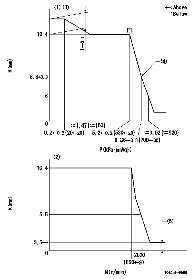
N:Pump speed
R:Rack position (mm)
P:Negative pressure
(1)Pneumatic governor
(2)Mechanical governor
(3)Acting negative pressure: P1
(4)Beginning of idle sub spring operation: L1
(5)Injection quantity Q = Q1 or less
----------
L1=6.8+0.3mm Q1=3mm3/st
----------
----------
L1=6.8+0.3mm Q1=3mm3/st
----------
Speed control lever angle
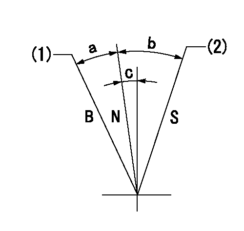
S:Stop
B:When boosted
N:Normal
(1)Rack position = aa
(2)Rack position bb
----------
aa=18mm bb=0mm
----------
a=13deg+-5deg b=22deg+-3deg c=0deg+-5deg
----------
aa=18mm bb=0mm
----------
a=13deg+-5deg b=22deg+-3deg c=0deg+-5deg
Timing setting

(1)Pump vertical direction
(2)Position of gear's standard threaded hole at No 1 cylinder's beginning of injection
(3)-
(4)-
----------
----------
a=(50deg)
----------
----------
a=(50deg)
Information:
Table 1
Service Tools
Part Number Part
Caterpillar Electronic Technician (ET)
6V-7070
9U-7330 Digital Multimeter
8T-3224 Needle Tip Group
7X-1710 Multimeter Probe Group
8T-8726 Adapter Cable Assembly
9U-7246 Connector Repair Kit
DT
4C-3406 Connector Repair Kit
4C-8195 Control Service Tool (Switch Box)
Illustration 1 g00774942
Connections for the Communication Adapter II and the Caterpillar Electronic Technician (ET)The components that are needed in order to use the Communication Adapter II and the Caterpillar Electronic Technician ( ET) in order to determine diagnostic codes are listed: (6) Cable (7) 171-4400 Communication Adapter II (8) Service diagnostic cable. (9) Current version of Cat ET software and an IBM-COMPATIBLE personal computerReferenceSee Special Publication, NEHS0758, "Communications Adapter II User's Manual Contains Software".Note: Caterpillar Electronic Technician (ET) is a software program that can be used on an IBM compatible personal computer. In order to use the Cat ET, order the following materials: Special Publication, JERD2124, "ET Single Use Program License", Special Publication, JEHP1026, "Information and Requirements Sheet", 7X-1425 Data Link Cable and the Data Subscription and Special Publication, JERD2142, "Data Subscription". The Special Publication, JEHP1026, "Information and Requirements Sheet" lists the required hardware and the features of the Cat ET.The Cat ET is not required in order to determine the diagnostic codes and the Cat ET is not required in order to clear the diagnostic codes. However, the process of determining the diagnostic codes is easier and faster by using the Cat ET. The Cat ET can also display information on the history of a diagnostic code and the parameter status of diagnostic codes. These features allow the Cat ET to be a useful tool for troubleshooting.The Cat ET is used to communicate to the electronic control module over the data link by connecting to the machine diagnostic connector. For more information and the locations of the connectors, see Troubleshooting, "Electrical Components and Connector Locations" and the Electrical System Schematic in your machine's Service Manual.For instructions on servicing Sure Seal connectors, see Special Instruction, SMHS7531. For instructions on servicing Deutsch connectors, see Special Instruction, SEHS9615.Use the digital multimeter for measuring resistance or for measuring voltage. For instructions about the use of the 6V-7070 Digital Multimeter, see Special Instruction, SEHS7734. The 7X-1710 Multimeter Probe measures the voltage at the connectors without disconnecting the connectors. The probe cables are pushed into the back of the connector along the wire. The 8T-8726 Adapter Cable has a breakout with 3 pins. The adapter cable is used for measurements in the sensor circuits.Note: Except for harness tests, using continuity testers such as the 8T-0500 Continuity Tester or voltage testers such as the 5P-7277 Voltage Tester is not recommended for today's Caterpillar electrical circuits.