Information injection-pump assembly
BOSCH
9 400 614 170
9400614170
ZEXEL
101451-9491
1014519491
NISSAN-DIESEL
16700T9017
16700t9017

Rating:
Service parts 101451-9491 INJECTION-PUMP ASSEMBLY:
1.
_
6.
COUPLING PLATE
7.
COUPLING PLATE
8.
_
9.
_
11.
Nozzle and Holder
12.
Open Pre:MPa(Kqf/cm2)
11.8(120)

15.
NOZZLE SET
Cross reference number
BOSCH
9 400 614 170
9400614170
ZEXEL
101451-9491
1014519491
NISSAN-DIESEL
16700T9017
16700t9017
Zexel num
Bosch num
Firm num
Name
9 400 614 170
16700T9017 NISSAN-DIESEL
INJECTION-PUMP ASSEMBLY
ED33 * K 14BC PE4A,5A, PE
ED33 * K 14BC PE4A,5A, PE
Calibration Data:
Adjustment conditions
Test oil
1404 Test oil ISO4113 or {SAEJ967d}
1404 Test oil ISO4113 or {SAEJ967d}
Test oil temperature
degC
40
40
45
Nozzle and nozzle holder
105780-8140
Bosch type code
EF8511/9A
Nozzle
105780-0000
Bosch type code
DN12SD12T
Nozzle holder
105780-2080
Bosch type code
EF8511/9
Opening pressure
MPa
17.2
Opening pressure
kgf/cm2
175
Injection pipe
Outer diameter - inner diameter - length (mm) mm 6-2-600
Outer diameter - inner diameter - length (mm) mm 6-2-600
Tester oil delivery pressure
kPa
157
157
157
Tester oil delivery pressure
kgf/cm2
1.6
1.6
1.6
Direction of rotation (viewed from drive side)
Right R
Right R
Injection timing adjustment
Direction of rotation (viewed from drive side)
Right R
Right R
Injection order
1-3-4-2
Pre-stroke
mm
2
1.95
2.05
Beginning of injection position
Drive side NO.1
Drive side NO.1
Difference between angles 1
Cal 1-3 deg. 90 89.5 90.5
Cal 1-3 deg. 90 89.5 90.5
Difference between angles 2
Cal 1-4 deg. 180 179.5 180.5
Cal 1-4 deg. 180 179.5 180.5
Difference between angles 3
Cyl.1-2 deg. 270 269.5 270.5
Cyl.1-2 deg. 270 269.5 270.5
Injection quantity adjustment
Adjusting point
-
Rack position
11.9
Pump speed
r/min
1750
1750
1750
Average injection quantity
mm3/st.
61.2
57.2
65.2
Max. variation between cylinders
%
0
-4
4
Fixing the rack
*
Injection quantity adjustment_02
Adjusting point
-
Rack position
12.3
Pump speed
r/min
1000
1000
1000
Average injection quantity
mm3/st.
57
56
58
Max. variation between cylinders
%
0
-2.5
2.5
Basic
*
Fixing the rack
*
Injection quantity adjustment_03
Adjusting point
-
Rack position
7.6+-0.5
Pump speed
r/min
300
300
300
Average injection quantity
mm3/st.
9.8
7.5
12.1
Max. variation between cylinders
%
0
-15
15
Fixing the rack
*
Timer adjustment
Pump speed
r/min
300--
Advance angle
deg.
0
0
0
Remarks
Start
Start
Timer adjustment_02
Pump speed
r/min
400
Advance angle
deg.
0.5
Timer adjustment_03
Pump speed
r/min
450
Advance angle
deg.
0.7
Timer adjustment_04
Pump speed
r/min
700
Advance angle
deg.
1
0.5
1.5
Timer adjustment_05
Pump speed
r/min
1500
Advance angle
deg.
5
4.5
5.5
Timer adjustment_06
Pump speed
r/min
1900
Advance angle
deg.
7.5
7
8
Remarks
Finish
Finish
Test data Ex:
Governor adjustment
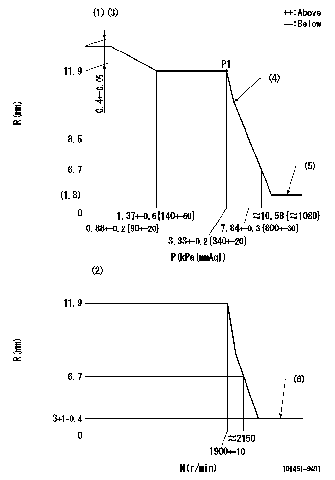
N:Pump speed
R:Rack position (mm)
P:Negative pressure
(1)Pneumatic governor
(2)Mechanical governor
(3)Acting negative pressure: P1
(4)Beginning of idle sub spring operation: L1
(5)Without stopper disk
(6)Injection quantity Q = Q1 or less
----------
L1=11.5+-0.3mm Q1=3mm3/st
----------
----------
L1=11.5+-0.3mm Q1=3mm3/st
----------
Speed control lever angle
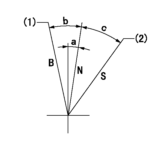
S:Stop
B:When boosted
N:Normal
(1)Rack position = aa
(2)Rack position bb
----------
aa=17.5mm bb=(1.8)mm
----------
a=7.5deg+-5deg b=10.5deg+-5deg c=21.5deg+-3deg
----------
aa=17.5mm bb=(1.8)mm
----------
a=7.5deg+-5deg b=10.5deg+-5deg c=21.5deg+-3deg
0000001501 ACS
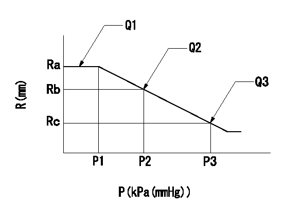
(P) Absolute pressure
(R) Rack position (mm)
1. Adjustment of the aneroid compensator
(1)Screw in the aneroid compensator body and attach the pushrod to the compensator lever so that the performance in the above graph can be obtained. The control lever must be at the full set position N = N1.
----------
N1=1000r/min
----------
Ra=12.3-0.05mm Rb=12.25mm Rc=11.6+-0.2mm P1=- P2=8-5.3kPa(60-40mmHg) P3=16.7kPa(125mmHg) Q1=- Q2=- Q3=-
----------
N1=1000r/min
----------
Ra=12.3-0.05mm Rb=12.25mm Rc=11.6+-0.2mm P1=- P2=8-5.3kPa(60-40mmHg) P3=16.7kPa(125mmHg) Q1=- Q2=- Q3=-
Timing setting

(1)Pump vertical direction
(2)Position of gear mark 'K' at No 1 cylinder's beginning of injection
(3)B.T.D.C.: aa
(4)-
----------
aa=12deg
----------
a=(50deg)
----------
aa=12deg
----------
a=(50deg)
Information:
Introduction
The problem that is identified below does not have a known permanent solution. Until a permanent solution is known, use the solution that is identified below.Problem
There have been some instances of the following active diagnostic codes:
651-6 Engine Injector Cylinder #01 : Current Above Normal
652-6 Engine Injector Cylinder #02 : Current Above Normal
653-6 Engine Injector Cylinder #03 : Current Above Normal
654-6 Engine Injector Cylinder #04 : Current Above NormalThe engine will be derated and will be difficult to start.Solution
Follow the correct troubleshooting procedure for the active diagnostic codes. Refer to Troubleshooting, Injector Solenoid - Test.
If the troubleshooting procedure identifies suspect injectors, use the electronic service tool to generate a Product Status Report (PSR). Select the "Histogram" option when generating the PSR.
Install replacement 418-3229 Fuel Injector Gp, as required. Refer to Disassembly and Assembly, Electronic Unit Injector - Remove and Disassembly and Assembly, Electronic Unit Injector - Install.
Use 169-7372 Fluid Sampling Bottles to obtain a fuel sample from the following locations:
Machine fuel tank ( 355 mL (12 oz)
Bulk fuel supply tank ( 355 mL (12 oz)Analyze the fuel sample. The fuel samples will need to be analyzed for the following properties:
Lubricity Wear Scar - "ASTM D6079" or "ISO 12156"
Density at 15° C (59° F) - "ASTM D1298", "ASTM D4052", "ISO 3675", or "ISO 12185"
Kinematic Viscosity at 40° C (104° F) - "ASTM D445", "ISO 3448", or "ISO 3104"
Sulfur - "ASTM D4294", "ASTM D5185", "ASTM D5453", "ASTM D26222", "ISO 20846", or "ISO 20884"
Water by Distillation - "ASTM D95", "ASTM D6304", "ASTM D2709", "ASTM D1796", or "ISO3734"
Cloud Point - "ASTM D2500" or "ISO 3015"
FAME - "EN 14078", "ASTM D7806", or "ASTM D7371"
Oxidation Stability - "EN 14112"
Copper - "ASTM D7111"
Sodium - "ASTM D7111"
Zinc - "ASTM D7111"
Calcium - "ASTM D7111"
Potassium - "ASTM D7111"Provide the results of the fuel sample.
Retain any removed injectors. The injectors will be requested for return through the "Send It Back" (SIB) process.
Submit the PSR along with TIB Media number, M0085259, and CPI number 386169 through "CPI Feedback" within the Service Information Management System (SIMSi).