Information injection-pump assembly
BOSCH
9 400 614 169
9400614169
ZEXEL
101451-9471
1014519471
NISSAN-DIESEL
16700T9015
16700t9015

Rating:
Service parts 101451-9471 INJECTION-PUMP ASSEMBLY:
1.
_
6.
COUPLING PLATE
7.
COUPLING PLATE
8.
_
9.
_
11.
Nozzle and Holder
1660036W00
12.
Open Pre:MPa(Kqf/cm2)
9.8{100}

15.
NOZZLE SET
Cross reference number
BOSCH
9 400 614 169
9400614169
ZEXEL
101451-9471
1014519471
NISSAN-DIESEL
16700T9015
16700t9015
Zexel num
Bosch num
Firm num
Name
9 400 614 169
16700T9015 NISSAN-DIESEL
INJECTION-PUMP ASSEMBLY
ED33 K 14BC INJECTION PUMP ASSY PE4A,5A, PE
ED33 K 14BC INJECTION PUMP ASSY PE4A,5A, PE
Calibration Data:
Adjustment conditions
Test oil
1404 Test oil ISO4113 or {SAEJ967d}
1404 Test oil ISO4113 or {SAEJ967d}
Test oil temperature
degC
40
40
45
Nozzle and nozzle holder
105780-8140
Bosch type code
EF8511/9A
Nozzle
105780-0000
Bosch type code
DN12SD12T
Nozzle holder
105780-2080
Bosch type code
EF8511/9
Opening pressure
MPa
17.2
Opening pressure
kgf/cm2
175
Injection pipe
Outer diameter - inner diameter - length (mm) mm 6-2-600
Outer diameter - inner diameter - length (mm) mm 6-2-600
Tester oil delivery pressure
kPa
157
157
157
Tester oil delivery pressure
kgf/cm2
1.6
1.6
1.6
Direction of rotation (viewed from drive side)
Right R
Right R
Injection timing adjustment
Direction of rotation (viewed from drive side)
Right R
Right R
Injection order
1-3-4-2
Pre-stroke
mm
2
1.95
2.05
Beginning of injection position
Drive side NO.1
Drive side NO.1
Difference between angles 1
Cal 1-3 deg. 90 89.5 90.5
Cal 1-3 deg. 90 89.5 90.5
Difference between angles 2
Cal 1-4 deg. 180 179.5 180.5
Cal 1-4 deg. 180 179.5 180.5
Difference between angles 3
Cyl.1-2 deg. 270 269.5 270.5
Cyl.1-2 deg. 270 269.5 270.5
Injection quantity adjustment
Adjusting point
-
Rack position
11.9
Pump speed
r/min
1750
1750
1750
Average injection quantity
mm3/st.
61.2
57.2
65.2
Max. variation between cylinders
%
0
-4
4
Fixing the rack
*
Injection quantity adjustment_02
Adjusting point
-
Rack position
12.3
Pump speed
r/min
1000
1000
1000
Average injection quantity
mm3/st.
57
56
58
Max. variation between cylinders
%
0
-2.5
2.5
Basic
*
Fixing the rack
*
Injection quantity adjustment_03
Adjusting point
-
Rack position
7.6+-0.5
Pump speed
r/min
300
300
300
Average injection quantity
mm3/st.
9.8
7.5
12.1
Max. variation between cylinders
%
0
-15
15
Fixing the rack
*
Timer adjustment
Pump speed
r/min
300++
Advance angle
deg.
0
0
0
Remarks
Start
Start
Timer adjustment_02
Pump speed
r/min
400
Advance angle
deg.
0.5
Timer adjustment_03
Pump speed
r/min
450
Advance angle
deg.
0.7
Timer adjustment_04
Pump speed
r/min
700
Advance angle
deg.
1
0.5
1.5
Timer adjustment_05
Pump speed
r/min
1500
Advance angle
deg.
5
4.5
5.5
Timer adjustment_06
Pump speed
r/min
1900
Advance angle
deg.
7.5
7
8
Remarks
Finish
Finish
Test data Ex:
Governor adjustment
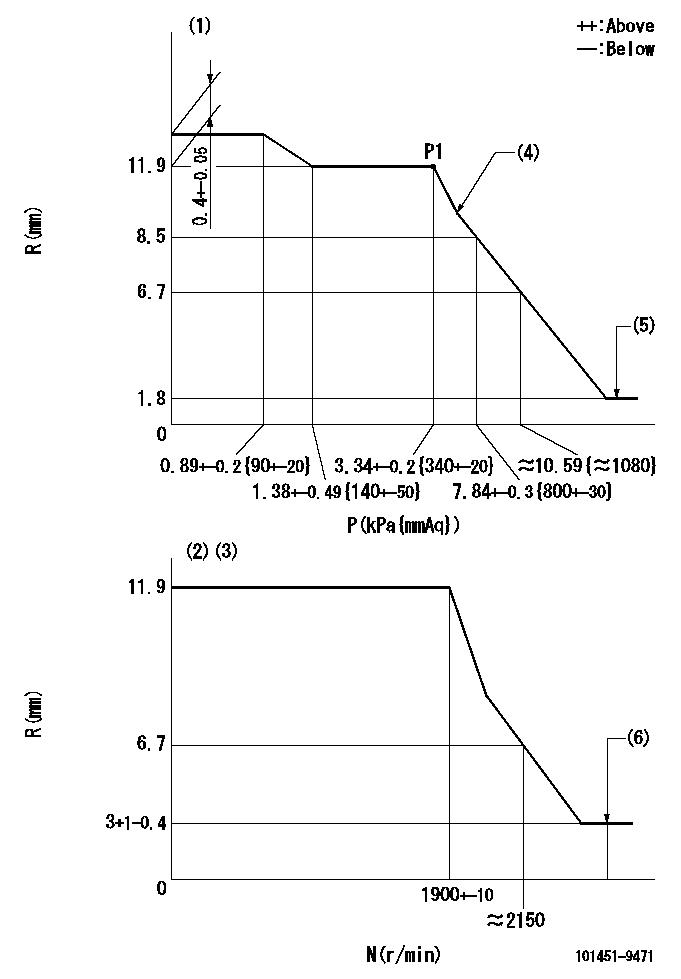
N:Pump speed
R:Rack position (mm)
P:Negative pressure
(1)Pneumatic governor
(2)Mechanical governor
(3)Acting negative pressure: P1
(4)Beginning of idle sub spring operation: L1
(5)With stopper disk.
(6)Injection quantity Q = Q1 or less
----------
L1=11.5+-0.3mm Q1=3mm3/st
----------
----------
L1=11.5+-0.3mm Q1=3mm3/st
----------
0000001101
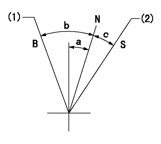
N:Normal
B:When boosted
S:Stop
(1)Rack position = aa
(2)Rack position bb
----------
aa=17.5mm bb=(1.8)mm
----------
a=7.5deg+-5deg b=10.5deg+-5deg c=21.5deg+-3deg
----------
aa=17.5mm bb=(1.8)mm
----------
a=7.5deg+-5deg b=10.5deg+-5deg c=21.5deg+-3deg
Timing setting

(1)Pump vertical direction
(2)Position of gear mark 'K' at No 1 cylinder's beginning of injection
(3)B.T.D.C.: aa
(4)-
----------
aa=12deg
----------
a=(50deg)
----------
aa=12deg
----------
a=(50deg)
Information:
Communicating with the Wireless Communication Adapter
Table 23 lists the optional hardware that is needed in order to connect Cat ET by using a wireless connection.
Table 23
Optional Hardware for the Use of Cat ET
Part Number Description
N/A Personal Computer (PC)
261-3363 (1) Wireless Communication Adapter Gp
( 1 ) Refer to Tool Operating Manual, "Using the 261-3363 Wireless Communication Adapter Gp " for information that is related to the installation and the configuration.
Illustration 81 g01297379
(1) Personal computer (PC) (7) 261-4867 Card (PCMCIA) (8) 239-9955 Communication Radio Gp (9) 259-3183 Data Link Cable As Note: Items (7), (8), and (9) are part of the 261-3363 Wireless Communication Adapter Gp .Use the following procedure in order to connect the wireless communication adapter for use with Cat ET.
Remove the electrical power from the ECM.
Ensure that the computer has been correctly configured for the 261-4867 Card (PCMCIA). Verify that the PC card is installed in the computer PCI expansion slot.
Connect cable (9) between communication radio (8) and the service tool connector.
Restore the electrical power to the ECM. If Cat ET and the communication radio do not communicate with the ECM, refer to troubleshooting without a diagnostic code Troubleshooting, "Electronic Service Tool Will Not Communicate with ECM".Starting System
The EUI system requires that the crankshaft rotate at a minimum of 70 rpm. The engine starting system must be able to supply the air pressure and flow to the starting motor in order to start the engine. The vane type starting motors may be replaced with turbine type starting motors.If the existing starting system does not meet the 70 rpm requirement, the starting motors must be replaced with turbine type starting motors. Refer to Table 24 for a list of part numbers for the recommended turbine type starting motors for 3600 Engines. For a dual starting motor application, two of the motor group part number must be ordered.Air lines to the starting motors must be modified for the turbine starters. A lubricating device is not required for the turbine type starting motors. Any lubricating device must be removed. The air lines for a single starting motor must have a minimum diameter of 38.1 mm (1.5 inch). Air lines for dual starting motors must have a minimum diameter of 76.2 mm (3.0 inch).
Table 24
Turbine Type Starting Motors for 3600 Engine Applications
Sales Model Standard Rotation Reverse Rotation Quantity
3606 and 3608 269-3839 275-8518 1
3612 (1) 295-6006 295-6007
246-1241 246-4483 2
3616
( 1 ) 3612 Engines can be started by dual starting motors or by a single starting motor. A single starting motor may only be used in cases when minimal parasitic torque is coupled to the engine during cranking. Dual starters may be required in applications when a 3612 Engine must be started in cold ambient conditions. Cold ambient condition will raise the viscosity of the