Information injection-pump assembly
ZEXEL
101451-9300
1014519300
NISSAN-DIESEL
16700J6504
16700j6504
Rating:
Service parts 101451-9300 INJECTION-PUMP ASSEMBLY:
1.
_
6.
COUPLING PLATE
7.
COUPLING PLATE
8.
_
9.
_
11.
Nozzle and Holder
16600-J6500
12.
Open Pre:MPa(Kqf/cm2)
11.8{120}

15.
NOZZLE SET
Cross reference number
ZEXEL
101451-9300
1014519300
NISSAN-DIESEL
16700J6504
16700j6504
Zexel num
Bosch num
Firm num
Name
101451-9300
16700J6504 NISSAN-DIESEL
INJECTION-PUMP ASSEMBLY
ED33 * K
ED33 * K
Calibration Data:
Adjustment conditions
Test oil
1404 Test oil ISO4113 or {SAEJ967d}
1404 Test oil ISO4113 or {SAEJ967d}
Test oil temperature
degC
40
40
45
Nozzle and nozzle holder
105780-8140
Bosch type code
EF8511/9A
Nozzle
105780-0000
Bosch type code
DN12SD12T
Nozzle holder
105780-2080
Bosch type code
EF8511/9
Opening pressure
MPa
17.2
Opening pressure
kgf/cm2
175
Injection pipe
Outer diameter - inner diameter - length (mm) mm 6-2-600
Outer diameter - inner diameter - length (mm) mm 6-2-600
Tester oil delivery pressure
kPa
157
157
157
Tester oil delivery pressure
kgf/cm2
1.6
1.6
1.6
Direction of rotation (viewed from drive side)
Right R
Right R
Injection timing adjustment
Direction of rotation (viewed from drive side)
Right R
Right R
Injection order
1-3-4-2
Pre-stroke
mm
2
1.95
2.05
Beginning of injection position
Drive side NO.1
Drive side NO.1
Difference between angles 1
Cal 1-3 deg. 90 89.5 90.5
Cal 1-3 deg. 90 89.5 90.5
Difference between angles 2
Cal 1-4 deg. 180 179.5 180.5
Cal 1-4 deg. 180 179.5 180.5
Difference between angles 3
Cyl.1-2 deg. 270 269.5 270.5
Cyl.1-2 deg. 270 269.5 270.5
Injection quantity adjustment
Adjusting point
-
Rack position
12.2
Pump speed
r/min
1000
1000
1000
Average injection quantity
mm3/st.
55.2
54.2
56.2
Max. variation between cylinders
%
0
-2.4
2.4
Basic
*
Fixing the rack
*
Injection quantity adjustment_02
Adjusting point
-
Rack position
7.7+-0.5
Pump speed
r/min
300
300
300
Average injection quantity
mm3/st.
10.6
8.3
12.9
Max. variation between cylinders
%
0
-15
15
Fixing the rack
*
Injection quantity adjustment_03
Adjusting point
-
Rack position
-
Pump speed
r/min
1000
1000
1000
Average injection quantity
mm3/st.
55.2
54.7
55.7
Remarks
Smoke setting
Smoke setting
Timer adjustment
Pump speed
r/min
300--
Advance angle
deg.
0
0
0
Remarks
Start
Start
Timer adjustment_02
Pump speed
r/min
400
Advance angle
deg.
0.5
Timer adjustment_03
Pump speed
r/min
450
Advance angle
deg.
0.7
Timer adjustment_04
Pump speed
r/min
700
Advance angle
deg.
1
0.5
1.5
Timer adjustment_05
Pump speed
r/min
1500
Advance angle
deg.
5
4.5
5.5
Timer adjustment_06
Pump speed
r/min
1900
Advance angle
deg.
7.5
7
8
Remarks
Finish
Finish
Test data Ex:
Governor adjustment
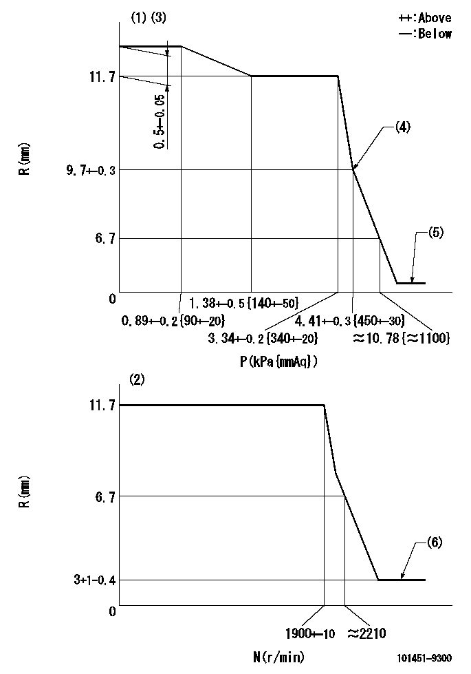
N:Pump speed
R:Rack position (mm)
P:Negative pressure
(1)Pneumatic governor
(2)Mechanical governor
(3)Acting negative pressure: P1
(4)Beginning of idle sub spring operation: L1
(5)With stop device.
(6)Injection quantity Q = Q1 or less
----------
L1=9.7+-0.3mm Q1=3mm3/st
----------
----------
L1=9.7+-0.3mm Q1=3mm3/st
----------
Speed control lever angle
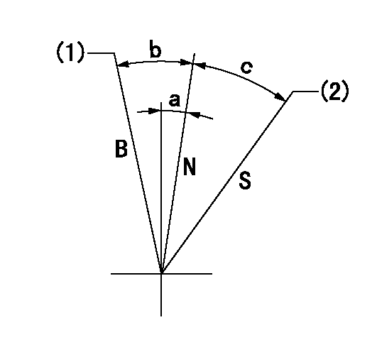
B:When boosted
N:Normal
S:Stop
(1)Rack position = aa
(2)Rack position bb
----------
aa=16mm bb=(1.8)mm
----------
a=7.5deg+-5deg b=7deg+-5deg c=21.5deg+-3deg
----------
aa=16mm bb=(1.8)mm
----------
a=7.5deg+-5deg b=7deg+-5deg c=21.5deg+-3deg
0000001501 ACS
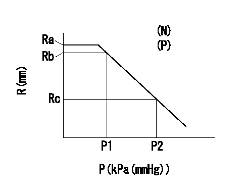
(N): Speed of the pump
(P): governor's negative pressure
(R) Rack position (mm)
Aneroid compensator adjustment
(1)Screw in the aneroid compensator body to obtain the performance shown in the graph above.
----------
----------
N=1000r/min P=0.69kPa(70mmAq) Ra=R1(12.2-0.05)mm Rb=R1-0.05mm Rc=11.6+-0.2mm P1=8-5.3kPa(60-40mmHg) P2=16.7kPa(125mmHg)
----------
----------
N=1000r/min P=0.69kPa(70mmAq) Ra=R1(12.2-0.05)mm Rb=R1-0.05mm Rc=11.6+-0.2mm P1=8-5.3kPa(60-40mmHg) P2=16.7kPa(125mmHg)
Timing setting

(1)Pump vertical direction
(2)Position of gear mark '0' at No 1 cylinder's beginning of injection
(3)B.T.D.C.: aa
(4)-
----------
aa=12deg
----------
a=(50deg)
----------
aa=12deg
----------
a=(50deg)
Information:
If the procedure did not correct the issue, contact your Cat dealer Technical Communicator (TC). For further assistance, your TC can confer with the Dealer Solutions Network (DSN).E1156(1) - Filter intake pressure greater than 10 kPa (1.50 psi) for more than 10 seconds. Refer to Table14 for troubleshooting.E1156(2) - Filter intake pressure greater than 15 kPa (2.25 psi) for more than 10 seconds. Refer to Table14 for troubleshooting.A faulty sensor may cause this diagnostic code. First determine that the sensor is not faulty.
Table 14
Troubleshooting Test Steps Values Results
1. Check for Associated Diagnostic Codes.
A. Establish communication between the Cat® Electronic Technician (ET) and the engine Electronic Control Module (ECM).
B. Troubleshoot any associated diagnostic codes that are present before continuing with this procedure.
Associated Diagnostic Codes
Result: An associated diagnostic code is not present.
Proceed to Test Step 2.
Result: An associated diagnostic code is active or logged.
1. Troubleshoot the associated diagnostic code before continuing with this procedure.
2. Service Maintenance.
A. Determine the most recent cleaning of the Wall Flow Filter (WFF).
Cleaning Interval
Result: The WFF was cleaned within the last 1000 hours.
Proceed to Test Step 3.
Result: The WFF was not cleaned within the last 1000 hours.
Proceed to Test Step 4.
3. Check for Contamination.
A. Reset all active codes and clear all logged codes.
B. Remove the WFF.
C. Check for contamination on the face of the WFF.
Contamination
Result: There is no sign of oil, fuel, or coolant on the WFF.
Proceed to Test Step 4.
Result: There is oil, fuel, or coolant on the WFF.
1. Diagnose the cause of the contamination.
2. The engine must be run with no load at 1400 rpm for at least 15 minutes, or until there is no white smoke.
3. If white smoke continues, or if the diagnostic code remains active, proceed to Test Step 5.
4. Clean the WFF.
A. Clean the WFF. Refer to "Wall Flow Diesel Particulate Filter - Clean".
B. Reset all active codes and clear all logged codes.
Clean was successful
Result: Cleaning the WFF was successful.
Return the machine to service.
Result: Cleaning the WFF was not successful.
1. Troubleshoot any diagnostic codes that are present, if no codes are present, proceed to Test Step 6.
5. Replace the WFF.
Replacement was successful
Result: Replacing the WFF was successful.
Return the machine to service.
If the procedure did not correct the issue, contact your Cat dealer Technical Communicator (TC). For further assistance, your TC can confer with the Dealer Solutions Network (DSN).Exhaust Temperature Is High
Certain operating conditions may cause the exhaust temperature to increase to a level that may damage engine components.Probable Causes
Boost Leak
Engine operating conditions
High altitude
Obstructed aftercooler
Table 15
Troubleshooting Test Steps Values Results
1. Check for Boost Leakage.
A. Apply a light load to the engine and check for boost leakage.
Boost Leaks
Result: Boost leakage was found.
Repair: Repair the leaks. Return the machine to service.
Result: Boost leakage was not found.
Proceed to Test Step 2.
2. Check the Engine Operating Conditions.
A. Check the histogram to determine if the high exhaust temperature was due to normal operation.
When possible, interview the operator. Determine if the engine is being operated under heavy load. Ensure that the engine is being operated at the
Have questions with 101451-9300?
Group cross 101451-9300 ZEXEL
Nissan-Diesel
101451-9300
16700J6504
INJECTION-PUMP ASSEMBLY
ED33
ED33