Information injection-pump assembly
ZEXEL
101451-9290
1014519290
NISSAN-DIESEL
16700J6503
16700j6503

Rating:
Service parts 101451-9290 INJECTION-PUMP ASSEMBLY:
1.
_
6.
COUPLING PLATE
7.
COUPLING PLATE
8.
_
9.
_
11.
Nozzle and Holder
16600-J6500
12.
Open Pre:MPa(Kqf/cm2)
11.8{120}
15.
NOZZLE SET
Cross reference number
ZEXEL
101451-9290
1014519290
NISSAN-DIESEL
16700J6503
16700j6503
Zexel num
Bosch num
Firm num
Name
101451-9290
16700J6503 NISSAN-DIESEL
INJECTION-PUMP ASSEMBLY
ED33 * K
ED33 * K
Calibration Data:
Adjustment conditions
Test oil
1404 Test oil ISO4113 or {SAEJ967d}
1404 Test oil ISO4113 or {SAEJ967d}
Test oil temperature
degC
40
40
45
Nozzle and nozzle holder
105780-8140
Bosch type code
EF8511/9A
Nozzle
105780-0000
Bosch type code
DN12SD12T
Nozzle holder
105780-2080
Bosch type code
EF8511/9
Opening pressure
MPa
17.2
Opening pressure
kgf/cm2
175
Injection pipe
Outer diameter - inner diameter - length (mm) mm 6-2-600
Outer diameter - inner diameter - length (mm) mm 6-2-600
Tester oil delivery pressure
kPa
157
157
157
Tester oil delivery pressure
kgf/cm2
1.6
1.6
1.6
Direction of rotation (viewed from drive side)
Right R
Right R
Injection timing adjustment
Direction of rotation (viewed from drive side)
Right R
Right R
Injection order
1-3-4-2
Pre-stroke
mm
2
1.95
2.05
Beginning of injection position
Drive side NO.1
Drive side NO.1
Difference between angles 1
Cal 1-3 deg. 90 89.5 90.5
Cal 1-3 deg. 90 89.5 90.5
Difference between angles 2
Cal 1-4 deg. 180 179.5 180.5
Cal 1-4 deg. 180 179.5 180.5
Difference between angles 3
Cyl.1-2 deg. 270 269.5 270.5
Cyl.1-2 deg. 270 269.5 270.5
Injection quantity adjustment
Adjusting point
-
Rack position
11.9
Pump speed
r/min
1750
1750
1750
Average injection quantity
mm3/st.
60.3
58.3
62.3
Max. variation between cylinders
%
0
-4
4
Fixing the rack
*
Injection quantity adjustment_02
Adjusting point
-
Rack position
12.4
Pump speed
r/min
1000
1000
1000
Average injection quantity
mm3/st.
56.7
55.7
57.7
Max. variation between cylinders
%
0
-2.5
2.5
Basic
*
Fixing the rack
*
Injection quantity adjustment_03
Adjusting point
-
Rack position
8.4+-0.5
Pump speed
r/min
300
300
300
Average injection quantity
mm3/st.
15
12.7
17.3
Max. variation between cylinders
%
0
-15
15
Fixing the rack
*
Injection quantity adjustment_04
Adjusting point
-
Rack position
-
Pump speed
r/min
1000
1000
1000
Average injection quantity
mm3/st.
56.7
56.2
57.2
Remarks
Smoke setting
Smoke setting
Timer adjustment
Pump speed
r/min
300++
Advance angle
deg.
0
0
0
Remarks
Start
Start
Timer adjustment_02
Pump speed
r/min
400
Advance angle
deg.
0.5
Timer adjustment_03
Pump speed
r/min
450
Advance angle
deg.
0.7
Timer adjustment_04
Pump speed
r/min
700
Advance angle
deg.
1
0.5
1.5
Timer adjustment_05
Pump speed
r/min
1500
Advance angle
deg.
5
4.5
5.5
Timer adjustment_06
Pump speed
r/min
1900
Advance angle
deg.
7.5
7
8
Remarks
Finish
Finish
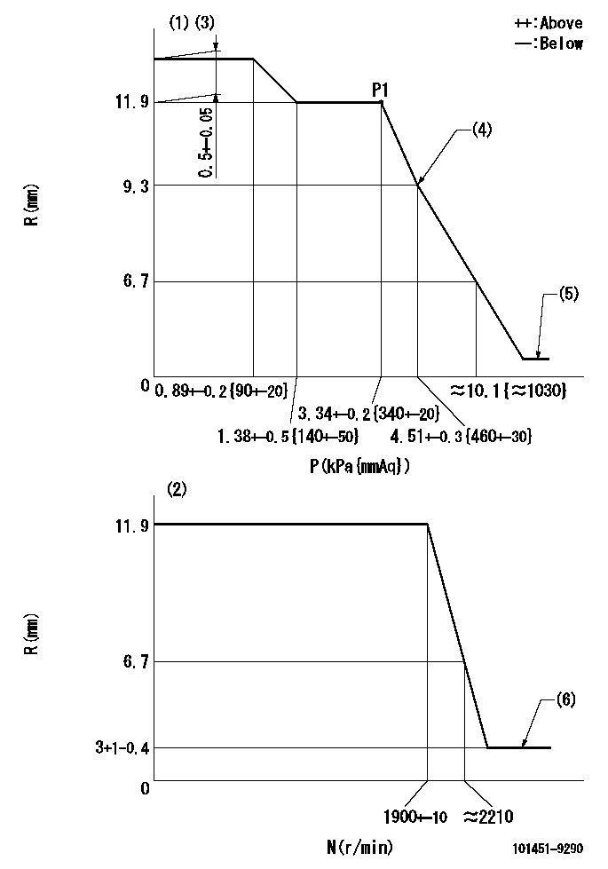
Test data Ex:
Governor adjustment

N:Pump speed
R:Rack position (mm)
P:Negative pressure
(1)Pneumatic governor
(2)Mechanical governor
(3)Acting negative pressure: P1
(4)Beginning of idle sub spring operation: L1
(5)With stop device.
(6)Injection quantity Q = Q1 or less
----------
L1=9.3+-0.3mm Q1=3mm3/st
----------
----------
L1=9.3+-0.3mm Q1=3mm3/st
----------
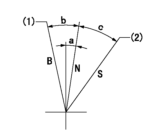
Speed control lever angle

B:When boosted
N:Normal
S:Stop
(1)Rack position = aa
(2)Rack position bb
----------
aa=17.5mm bb=(1.8)mm
----------
a=7.5deg+-5deg b=10.5deg+-5deg c=21.5deg+-3deg
----------
aa=17.5mm bb=(1.8)mm
----------
a=7.5deg+-5deg b=10.5deg+-5deg c=21.5deg+-3deg
Timing setting

(1)Pump vertical direction
(2)Position of gear mark 'P' at No 1 cylinder's beginning of injection
(3)B.T.D.C.: aa
(4)-
----------
aa=12deg
----------
a=(50deg)
----------
aa=12deg
----------
a=(50deg)
Information:
Repeat Steps 8 and 9 until the system is completely clean.
Fill the cooling system with the Cat ELC.
Operate the engine until the engine is warmed. While the engine is running, inspect the engine for leaks. Tighten hose clamps and connections in order to stop any leaks.
Attach the Special Publication, PMEP5027, "Label" to the cooling system filler for the engine in order to indicate the use of Cat ELC.Note: Clean water is the only flushing agent that is required when Cat ELC is drained from the cooling system.
A Level II coolant analysis by S O S Services is recommended after changing over to Cat ELC in order to ensure proper additive levels are present and in order to ensure there are no excessive levels of physical and chemical contaminantsCat ELC Cooling System Contamination
Mixing other products with Cat ELC reduces the effectiveness of the Cat ELC and shortens the Cat ELC service life. Use only Cat ELC Extender with Cat ELC. Failure to follow these recommendations can result in shortened cooling system component life.
Cat ELC cooling systems can withstand contamination to a maximum of ten percent of conventional heavy-duty coolant/antifreeze and/or SCA before the advantages of Cat ELC are reduced. If the contamination exceeds ten percent of the total system capacity; perform ONE of the following procedures:
If the cooling system contamination is caused by cooling system damage, follow the procedures under the "Changing to Cat ELC" heading. Also follow the procedures under the "Changing to Cat ELC" heading if the engine has been operated since being contaminated with more than ten percent conventional heavy-duty coolant/antifreeze and/or SCA. Certain types of cooling system contamination may require disassembly of the cooling system and manual cleaning of system components.
If the cooling system is contaminated with more than ten percent conventional heavy-duty coolant/antifreeze and/or SCA, but the engine has not been operated, drain the cooling system into a suitable container. Dispose of the coolant according to local regulations. Thoroughly flush the system with clean water. Fill the system with the Cat ELC.
Maintain the system as a conventional DEAC (Diesel Engine Antifreeze/Coolant) or other conventional coolant. If the SCA concentration is less than three percent, treat the system with an SCA. Maintain a three to six percent SCA concentration in the coolant. Change the coolant at the interval that is recommended for Cat DEAC or at the interval that is recommended for the conventional commercial coolants.
Do Not Mix Brands and/or Types of Products.Mixing other products with Cat ELC reduces the effectiveness of the Cat ELC and shortens the Cat ELC service life. Use only Cat products or commercial products that have passed the Caterpillar EC-1 specification for premixed or concentrate coolants, and that have also passed the additional requirements for EC-1 as found in the coolant section of this Special Publication. Use only Cat ELC Extender with Cat ELC. Do NOT mix brands or types of coolants. Do NOT mix brands or types of SCA. Do NOT mix brands or types of extenders. Do NOT
Have questions with 101451-9290?
Group cross 101451-9290 ZEXEL
Nissan-Diesel
Nissan-Diesel
101451-9290
16700J6503
INJECTION-PUMP ASSEMBLY
ED33
ED33
