Information injection-pump assembly
ZEXEL
101451-9140
1014519140
NISSAN-DIESEL
16700J5504
16700j5504

Rating:
Service parts 101451-9140 INJECTION-PUMP ASSEMBLY:
1.
_
6.
COUPLING PLATE
7.
COUPLING PLATE
8.
_
9.
_
11.
Nozzle and Holder
16600-Z5000
12.
Open Pre:MPa(Kqf/cm2)
11.8{120}
15.
NOZZLE SET
Cross reference number
ZEXEL
101451-9140
1014519140
NISSAN-DIESEL
16700J5504
16700j5504
Zexel num
Bosch num
Firm num
Name
101451-9140
16700J5504 NISSAN-DIESEL
INJECTION-PUMP ASSEMBLY
ED30 * K
ED30 * K
Calibration Data:
Adjustment conditions
Test oil
1404 Test oil ISO4113 or {SAEJ967d}
1404 Test oil ISO4113 or {SAEJ967d}
Test oil temperature
degC
40
40
45
Nozzle and nozzle holder
105780-8140
Bosch type code
EF8511/9A
Nozzle
105780-0000
Bosch type code
DN12SD12T
Nozzle holder
105780-2080
Bosch type code
EF8511/9
Opening pressure
MPa
17.2
Opening pressure
kgf/cm2
175
Injection pipe
Outer diameter - inner diameter - length (mm) mm 6-2-600
Outer diameter - inner diameter - length (mm) mm 6-2-600
Tester oil delivery pressure
kPa
157
157
157
Tester oil delivery pressure
kgf/cm2
1.6
1.6
1.6
Direction of rotation (viewed from drive side)
Right R
Right R
Injection timing adjustment
Direction of rotation (viewed from drive side)
Right R
Right R
Injection order
1-3-4-2
Pre-stroke
mm
2.35
2.3
2.4
Rack position
R=13.6
Beginning of injection position
Drive side NO.1
Drive side NO.1
Difference between angles 1
Cal 1-3 deg. 90 89.5 90.5
Cal 1-3 deg. 90 89.5 90.5
Difference between angles 2
Cal 1-4 deg. 180 179.5 180.5
Cal 1-4 deg. 180 179.5 180.5
Difference between angles 3
Cyl.1-2 deg. 270 269.5 270.5
Cyl.1-2 deg. 270 269.5 270.5
Injection quantity adjustment
Adjusting point
-
Rack position
13.6
Pump speed
r/min
1750
1750
1750
Average injection quantity
mm3/st.
61
59
63
Max. variation between cylinders
%
0
-4
4
Fixing the rack
*
Injection quantity adjustment_02
Adjusting point
-
Rack position
13.6
Pump speed
r/min
1000
1000
1000
Average injection quantity
mm3/st.
54
53
55
Max. variation between cylinders
%
0
-2.5
2.5
Basic
*
Fixing the rack
*
Injection quantity adjustment_03
Adjusting point
-
Rack position
13.6
Pump speed
r/min
700
700
700
Average injection quantity
mm3/st.
51.7
49.7
53.7
Max. variation between cylinders
%
0
-4
4
Fixing the rack
*
Injection quantity adjustment_04
Adjusting point
-
Rack position
13.6
Pump speed
r/min
400
400
400
Average injection quantity
mm3/st.
48.3
46.3
50.3
Max. variation between cylinders
%
0
-4
4
Fixing the rack
*
Injection quantity adjustment_05
Adjusting point
-
Rack position
9.5+-0.5
Pump speed
r/min
300
300
300
Average injection quantity
mm3/st.
11.7
9.9
13.5
Max. variation between cylinders
%
0
-15
15
Fixing the rack
*
Injection quantity adjustment_06
Adjusting point
-
Rack position
-
Pump speed
r/min
1000
1000
1000
Average injection quantity
mm3/st.
54
53.5
54.5
Remarks
Smoke setting
Smoke setting
Timer adjustment
Pump speed
r/min
400+-50
Advance angle
deg.
0
0
0
Remarks
Start
Start
Timer adjustment_02
Pump speed
r/min
700
Advance angle
deg.
1.2
0.7
1.7
Timer adjustment_03
Pump speed
r/min
1100
Advance angle
deg.
3.5
3
4
Timer adjustment_04
Pump speed
r/min
1500
Advance angle
deg.
5.8
5.3
6.3
Timer adjustment_05
Pump speed
r/min
1800
Advance angle
deg.
7.5
7
8
Remarks
Finish
Finish
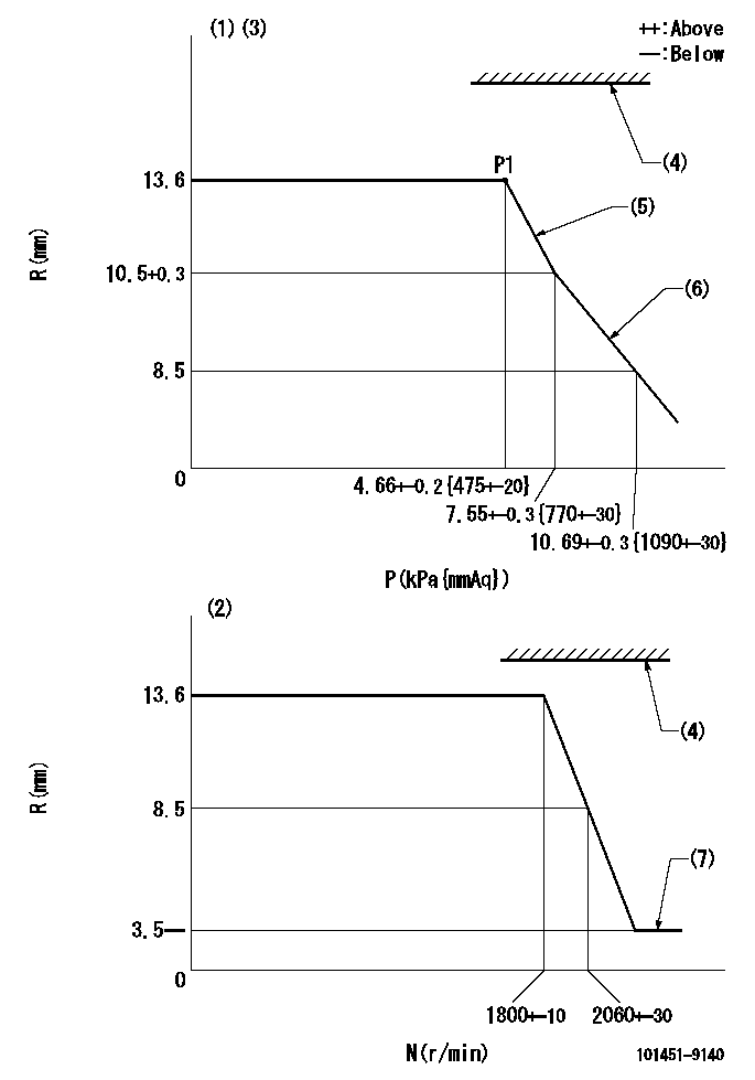
Test data Ex:
Governor adjustment

N:Pump speed
R:Rack position (mm)
P:Negative pressure
(1)Pneumatic governor
(2)Mechanical governor
(3)Acting negative pressure: P1
(4)RACK LIMIT: RAL
(5)Adjustment speed N1
(6)Beginning of idle sub spring operation: L1
(7)Injection quantity Q = Q1 or less
----------
RAL=18.5mm N1=500r/min L1=10.5+-0.3mm Q1=3mm3/st
----------
----------
RAL=18.5mm N1=500r/min L1=10.5+-0.3mm Q1=3mm3/st
----------
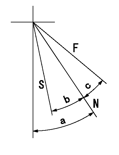
Speed control lever angle

F:Full speed
N:Normal
S:Stop
----------
----------
a=33deg+-5deg b=19deg+-3deg c=16.5deg+-5deg
----------
----------
a=33deg+-5deg b=19deg+-3deg c=16.5deg+-5deg
Timing setting

(1)Pump vertical direction
(2)Position of gear mark '0' at No 1 cylinder's beginning of injection
(3)-
(4)-
----------
----------
a=(50deg)
----------
----------
a=(50deg)
Information:
Table 1
S O S Oil Sampling Interval for Engine crankcase
Recommended Interval (1)(2) Oil Type
Every 250 Service Hours Cat DEO
Cat DEO-ULS
(1) Severe applications may require a more frequent oil sampling interval.
(2) Under certain conditions, the Cat dealer or the Operation and Maintenance Manual may allow a longer interval between oil samplings.Note: Refer to the Operation and Maintenance Manual for your engine for recommended oil drain intervals.Consult your Cat dealer for complete information and assistance in order to establish an S O S Services program for your engine.More Frequent S O S Sampling Improves Life Cycle Management
Traditionally, the suggested S O S sampling intervals for diesel engines have been at 250 hours. However in severe applications, more frequent oil sampling is recommended. Severe service for lubricated compartments occurs at high loads, in high temperatures, and in dusty conditions. If any of these conditions or other severe service indicators exist, sample the engine oil at 125 hour intervals. These additional samples will increase the chance of detecting a potential failure.Determining Optimum Oil Change Intervals
Sampling the engine oil at every 125 hours provides information for oil condition and for oil performance. This information is used to determine the optimum usable life of a particular oil. Also, more points of data will allow closer monitoring of component wear rates. Close monitoring also allows you to obtain the maximum use of the oil. For detailed information on optimizing oil change intervals, consult your Cat dealer.This Special Publication does not address recommended oil drain intervals. Refer to your engine Operation and Maintenance Manual, and consult your Cat dealer for additional guidance, including but not limited to guidance on establishing optimized and/or acceptable oil drain intervals.To reduce the potential risk of failures associated with extended oil drain periods, Caterpillar recommends that oil drain intervals only be extended based on oil analysis, and subsequent system inspections. Oil analysis alone does not provide an indication of the rate of formation of lacquer, varnish and/or other deposits on surfaces. The only accurate way to evaluate specific oil performance in a specific system using extended oil drain periods is to observe the effects on the system components. Making these observations involves tear-down inspections of systems that have run to the normal overhaul period while using extended oil drain intervals. Following this recommendation will help ensure that excessive component wear does not take place in a given application.Note: The use of Cat S O S Services oil analysis helps environmental sustainability as the best way to optimize oil life. S O S Services will help engines reach expected life. Consult your Cat dealer regarding the testing required to establish a safe, optimized oil drain interval.Standard oil drain intervals as published in engine Operation and Maintenance Manual are for typical applications:
Using recommended oils
Using good fuel
Using recommended filters
Using industry standard good maintenance practices
Following maintenance intervals as published in engine Operation and Maintenance ManualMore severe applications may require shortened oil drain intervals, while less severe applications may allow for longer than standard oil drain intervals. High
Have questions with 101451-9140?
Group cross 101451-9140 ZEXEL
Nissan-Diesel
101451-9140
16700J5504
INJECTION-PUMP ASSEMBLY
ED30
ED30
