Information injection-pump assembly
BOSCH
F 019 Z10 957
f019z10957
ZEXEL
101443-9080
1014439080
NISSAN-DIESEL
16790NA00B
16790na00b

Rating:
Service parts 101443-9080 INJECTION-PUMP ASSEMBLY:
1.
_
6.
COUPLING PLATE
7.
COUPLING PLATE
8.
_
9.
_
11.
Nozzle and Holder
12.
Open Pre:MPa(Kqf/cm2)
9.8(100)
15.
NOZZLE SET
Cross reference number
BOSCH
F 019 Z10 957
f019z10957
ZEXEL
101443-9080
1014439080
NISSAN-DIESEL
16790NA00B
16790na00b
Zexel num
Bosch num
Firm num
Name
101443-9080
F 019 Z10 957
16790NA00B NISSAN-DIESEL
INJECTION-PUMP ASSEMBLY
TD2704 K 14BC INJECTION PUMP ASSY PE4A,5A, PE
TD2704 K 14BC INJECTION PUMP ASSY PE4A,5A, PE
Calibration Data:
Adjustment conditions
Test oil
1404 Test oil ISO4113 or {SAEJ967d}
1404 Test oil ISO4113 or {SAEJ967d}
Test oil temperature
degC
40
40
45
Nozzle and nozzle holder
105780-8140
Bosch type code
EF8511/9A
Nozzle
105780-0000
Bosch type code
DN12SD12T
Nozzle holder
105780-2080
Bosch type code
EF8511/9
Opening pressure
MPa
17.2
Opening pressure
kgf/cm2
175
Injection pipe
Outer diameter - inner diameter - length (mm) mm 6-2-600
Outer diameter - inner diameter - length (mm) mm 6-2-600
Tester oil delivery pressure
kPa
157
157
157
Tester oil delivery pressure
kgf/cm2
1.6
1.6
1.6
Direction of rotation (viewed from drive side)
Right R
Right R
Injection timing adjustment
Direction of rotation (viewed from drive side)
Right R
Right R
Injection order
1-3-4-2
Pre-stroke
mm
2.15
2.1
2.2
Beginning of injection position
Drive side NO.1
Drive side NO.1
Difference between angles 1
Cal 1-3 deg. 90 89.5 90.5
Cal 1-3 deg. 90 89.5 90.5
Difference between angles 2
Cal 1-4 deg. 180 179.5 180.5
Cal 1-4 deg. 180 179.5 180.5
Difference between angles 3
Cyl.1-2 deg. 270 269.5 270.5
Cyl.1-2 deg. 270 269.5 270.5
Injection quantity adjustment
Adjusting point
A
Rack position
12.1
Pump speed
r/min
1000
1000
1000
Average injection quantity
mm3/st.
45.5
44.5
46.5
Max. variation between cylinders
%
0
-4
4
Basic
*
Fixing the lever
*
Injection quantity adjustment_02
Adjusting point
-
Rack position
8.5+-0.5
Pump speed
r/min
325
325
325
Average injection quantity
mm3/st.
8
6.9
9.1
Max. variation between cylinders
%
0
-10
10
Fixing the rack
*
Remarks
Adjust only variation between cylinders; adjust governor according to governor specifications.
Adjust only variation between cylinders; adjust governor according to governor specifications.
Injection quantity adjustment_03
Adjusting point
D
Rack position
12.5++
Pump speed
r/min
100
100
100
Average injection quantity
mm3/st.
55
50
60
Fixing the lever
*
Rack limit
*
Timer adjustment
Pump speed
r/min
(N1+50)-
-
Advance angle
deg.
0
0
0
Remarks
Start
Start
Timer adjustment_02
Pump speed
r/min
N1(540)
Advance angle
deg.
0.5
Timer adjustment_03
Pump speed
r/min
(700)
Advance angle
deg.
1.5
1.5
1.5
Timer adjustment_04
Pump speed
r/min
(880)
Advance angle
deg.
1.5
1.5
1.5
Timer adjustment_05
Pump speed
r/min
1150
Advance angle
deg.
2.5
2.5
2.5
Timer adjustment_06
Pump speed
r/min
1300
Advance angle
deg.
3.5
3.5
3.5
Timer adjustment_07
Pump speed
r/min
-
Advance angle
deg.
4
4
4
Remarks
Measure the actual speed, stop
Measure the actual speed, stop
Test data Ex:
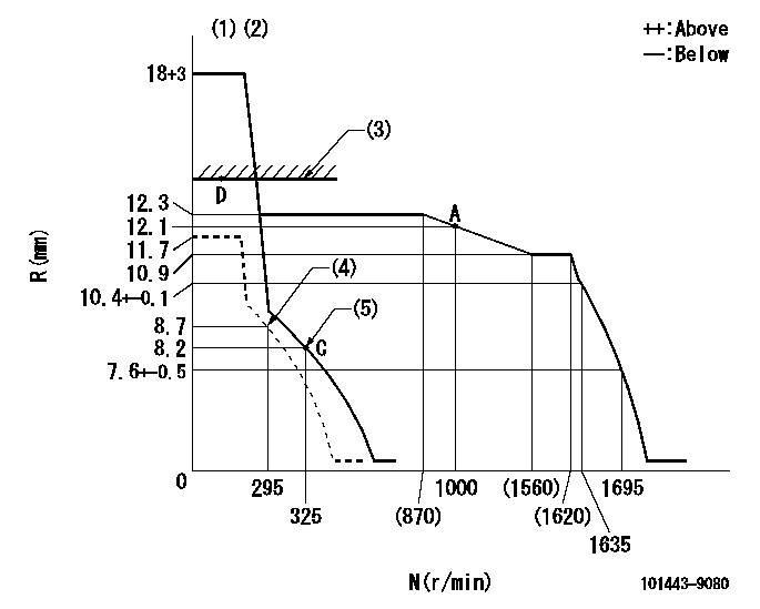
Governor adjustment

N:Pump speed
R:Rack position (mm)
(1)Target notch: K
(2)Tolerance for racks not indicated: +-0.05mm.
(3)RACK LIMIT
(4)Set idle sub-spring
(5)Main spring setting
----------
K=15
----------
----------
K=15
----------
Speed control lever angle

F:Full speed
I:Idle
(1)Stopper bolt setting
----------
----------
a=30deg+-5deg b=24deg+-5deg
----------
----------
a=30deg+-5deg b=24deg+-5deg
Stop lever angle

N:Pump normal
S:Stop the pump.
(1)Normal
----------
----------
a=12deg+-5deg b=53deg+-5deg
----------
----------
a=12deg+-5deg b=53deg+-5deg
0000001501 GOV FULL LOAD ADJUSTMENT

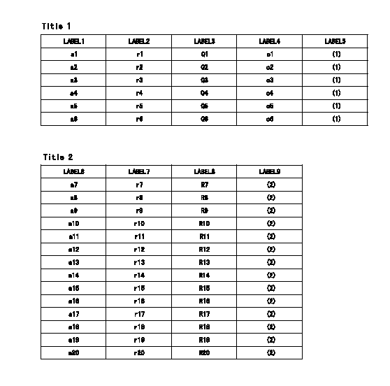
Title1:Full load stopper adjustment
Title2:Governor set speed
LABEL1:Distinguishing
LABEL2:Pump speed (r/min)
LABEL3:Ave. injection quantity (mm3/st)
LABEL4:Max. var. bet. cyl.
LABEL5:Remarks
LABEL6:Distinguishing
LABEL7:Governor set speed (r/min)
LABEL8:Maximum no-load speed (r/min)
LABEL9:Remarks
(1)Adjustment conditions are the same as those for measuring injection quantity.
(2)At high idle rack position L
----------
L=7.6mm
----------
a1=A a2=B a3=C a4=- a5=- a6=- r1=1000r/min r2=1000r/min r3=1000r/min r4=- r5=- r6=- Q1=- Q2=45.5+-1mm3/st Q3=- Q4=- Q5=- Q6=- c1=- c2=+-4% c3=- c4=- c5=- c6=- a7=32 a8=31 a9=30 a10=29 a11=28 a12=27 a13=26 a14=25 a15=24 a16=23 a17=22 a18=21 a19=20 a20=- r7=1600r/min r8=1550r/min r9=1500r/min r10=1450r/min r11=1400r/min r12=1350r/min r13=1300r/min r14=1250r/min r15=1200r/min r16=1150r/min r17=1100r/min r18=1050r/min r19=1000r/min r20=- R7=1720+-40r/min R8=1665+-38r/min R9=1610+-37r/min R10=1555+-36r/min R11=1505+-35r/min R12=1450+-33r/min R13=1395+-32r/min R14=1340+-31r/min R15=1290+-30r/min R16=1235+-28r/min R17=1180+-27r/min R18=1130+-26r/min R19=1075+-25r/min R20=-
----------
L=7.6mm
----------
a1=A a2=B a3=C a4=- a5=- a6=- r1=1000r/min r2=1000r/min r3=1000r/min r4=- r5=- r6=- Q1=- Q2=45.5+-1mm3/st Q3=- Q4=- Q5=- Q6=- c1=- c2=+-4% c3=- c4=- c5=- c6=- a7=32 a8=31 a9=30 a10=29 a11=28 a12=27 a13=26 a14=25 a15=24 a16=23 a17=22 a18=21 a19=20 a20=- r7=1600r/min r8=1550r/min r9=1500r/min r10=1450r/min r11=1400r/min r12=1350r/min r13=1300r/min r14=1250r/min r15=1200r/min r16=1150r/min r17=1100r/min r18=1050r/min r19=1000r/min r20=- R7=1720+-40r/min R8=1665+-38r/min R9=1610+-37r/min R10=1555+-36r/min R11=1505+-35r/min R12=1450+-33r/min R13=1395+-32r/min R14=1340+-31r/min R15=1290+-30r/min R16=1235+-28r/min R17=1180+-27r/min R18=1130+-26r/min R19=1075+-25r/min R20=-
Timing setting

(1)Pump vertical direction
(2)Position of gear mark 'ZZ' at No 1 cylinder's beginning of injection
(3)B.T.D.C.: aa
(4)-
----------
aa=16deg
----------
a=(100deg)
----------
aa=16deg
----------
a=(100deg)
Information:
Rework Procedure
This procedure is only required when utilizing the 444-2472 Bracket As or 444-2473 Bracket As, the former 222-6953 Valve Cover Bases, and the new stamped steel valve covers. Disregard if using 442-5727 Valve Cover Base.The preferred method to correct this issue is to remove the former 222-6953 Valve Cover Base and install the current 442-5727 Valve Cover Base. This valve cover base removes the need for the 444-2472 Bracket As and 444-2473 Bracket As.The alternative method is to modify the 444-2472 Bracket As or 444-2473 Bracket As to be used with the 222-6953 Valve Mechanism Cover Base and stamped steel valve cover.Note:
Illustration 1 g06088172
Bracket assemblies view
(1) 444-2472 Bracket As
(2) 444-2473 Bracket As
Illustration 2 g06088191
Side view of the bracket.
(3) Button portion
(4) Weld stud
Illustration 3 g06088192
Top view of the bracket.
The illustration above shows the location of the material that will need to be removed from the button of the bracket assemblies.
Illustration 4 g06088194
Side view of the bracket.
Illustration 5 g06088195
View of the bracket after modification.
Remove 4 mm (0.16 in) from the button on the bracket as shown in Illustration 4.
Once the additional material has been removed from the modified bracket, fit the valve cover to ensure that proper clearance has been created allowing sealing of valve cover PIP seal. Install and torque the valve cover using the appropriate procedure from the Disassembly and Assembly manual.
Illustration 6 g06088196
Impression made by bracket assemblies that contact the valve cover.
Remove the valve cover and inspect the mating surface to see if any contact marks are present as shown in Illustration 6. If contact marks are present, extra material of the button will need to be removed for clearance.
Have questions with 101443-9080?
Group cross 101443-9080 ZEXEL
Daewoo
Nissan-Diesel
Nissan-Diesel
Nissan-Diesel
Nissan-Diesel
101443-9080
F 019 Z10 957
16790NA00B
INJECTION-PUMP ASSEMBLY
TD2704
TD2704
