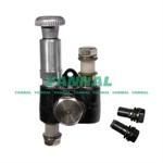
Information injection-pump assembly
BOSCH
9 400 614 156
9400614156
ZEXEL
101442-0091
1014420091
ISUZU
8944369921
8944369921

Rating:
Service parts 101442-0091 INJECTION-PUMP ASSEMBLY:
1.
_
5.
AUTOM. ADVANCE MECHANIS
6.
COUPLING PLATE
8.
_
9.
_
11.
Nozzle and Holder
8-94419-125-1
12.
Open Pre:MPa(Kqf/cm2)
13.7{140}
15.
NOZZLE SET
Include in #1:
101442-0091
as INJECTION-PUMP ASSEMBLY
Include in #2:
104740-0222
as _
Cross reference number
Zexel num
Bosch num
Firm num
Name
Information:
Remove The Fan
Illustration 1 g00871386
(1) Cable (2) Fan (3) Guard (4) Screws (5) Filter (6) Cover
Disconnect the power to the monitor.
Remove cover (6) and remove filter (5) .
Remove guard (3) by removing screws (4) that hold guard (3) in place.
Remove the back cover of the monitor by removing the 8 screws that hold the back cover in place. Refer to Testing And Adjusting, "Cover - Remove" for details on removing the back cover.
Remove the two wire ties that secure the power wires around fan (2) .
Illustration 2 g00871408
CPU Board (7) Connector
Follow cable (1) and disconnect the connector from CPU board (7). Disconnect the connector by pulling on the connector. Do not pull on the wires.
Remove fan (2) from the monitor.Install The Fan
Connect the connector of cable (1) to the CPU board (7) .
Position fan (2) so that the power wires are routed above fan (2) .
Secure fan (2) and secure guard (3) with screws (4) .
Replace filter (5) and replace cover (6) .
Secure the power wires to fan (2) by using the wire ties.
Replace the back cover of the monitor by using the 8 screws.
