Information injection-pump assembly
ZEXEL
101442-0080
1014420080
ISUZU
8944369910
8944369910

Rating:
Service parts 101442-0080 INJECTION-PUMP ASSEMBLY:
1.
_
3.
GOVERNOR

5.
AUTOM. ADVANCE MECHANIS
6.
COUPLING PLATE
7.
COUPLING PLATE
8.
_
9.
_
11.
Nozzle and Holder
8-94419-125-1
12.
Open Pre:MPa(Kqf/cm2)
13.7{140}
15.
NOZZLE SET
Include in #1:
101442-0080
as INJECTION-PUMP ASSEMBLY
Include in #2:
104740-0192
as _
Cross reference number
ZEXEL
101442-0080
1014420080
ISUZU
8944369910
8944369910
Zexel num
Bosch num
Firm num
Name
Calibration Data:
Adjustment conditions
Test oil
1404 Test oil ISO4113 or {SAEJ967d}
1404 Test oil ISO4113 or {SAEJ967d}
Test oil temperature
degC
40
40
45
Nozzle and nozzle holder
105780-8140
Bosch type code
EF8511/9A
Nozzle
105780-0000
Bosch type code
DN12SD12T
Nozzle holder
105780-2080
Bosch type code
EF8511/9
Opening pressure
MPa
17.2
Opening pressure
kgf/cm2
175
Injection pipe
Outer diameter - inner diameter - length (mm) mm 6-2-600
Outer diameter - inner diameter - length (mm) mm 6-2-600
Tester oil delivery pressure
kPa
157
157
157
Tester oil delivery pressure
kgf/cm2
1.6
1.6
1.6
Direction of rotation (viewed from drive side)
Right R
Right R
Injection timing adjustment
Direction of rotation (viewed from drive side)
Right R
Right R
Injection order
1-3-4-2
Pre-stroke
mm
1.95
1.9
2
Rack position
Point A R=A
Point A R=A
Beginning of injection position
Drive side NO.1
Drive side NO.1
Difference between angles 1
Cal 1-3 deg. 90 89.5 90.5
Cal 1-3 deg. 90 89.5 90.5
Difference between angles 2
Cal 1-4 deg. 180 179.5 180.5
Cal 1-4 deg. 180 179.5 180.5
Difference between angles 3
Cyl.1-2 deg. 270 269.5 270.5
Cyl.1-2 deg. 270 269.5 270.5
Injection quantity adjustment
Adjusting point
A
Rack position
6.2
Pump speed
r/min
1400
1400
1400
Average injection quantity
mm3/st.
29.7
28.7
30.7
Max. variation between cylinders
%
0
-2
2
Basic
*
Fixing the lever
*
Injection quantity adjustment_02
Adjusting point
-
Rack position
5.2+-0.5
Pump speed
r/min
425
425
425
Average injection quantity
mm3/st.
8
6.5
9.5
Max. variation between cylinders
%
0
-14
14
Fixing the rack
*
Remarks
Adjust only variation between cylinders; adjust governor according to governor specifications.
Adjust only variation between cylinders; adjust governor according to governor specifications.
Injection quantity adjustment_03
Adjusting point
C
Rack position
-
Pump speed
r/min
150
150
150
Average injection quantity
mm3/st.
55
55
65
Fixing the lever
*
Rack limit
*
Test data Ex:
Governor adjustment
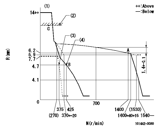
N:Pump speed
R:Rack position (mm)
(1)Target notch: K
(2)RACK LIMIT
(3)Set idle sub-spring
(4)Main spring setting
----------
K=16
----------
----------
K=16
----------
Speed control lever angle
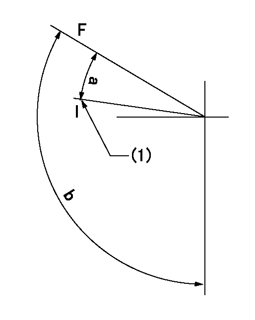
F:Full speed
I:Idle
(1)Stopper bolt setting
----------
----------
a=26deg+-5deg b=116deg+-5deg
----------
----------
a=26deg+-5deg b=116deg+-5deg
Stop lever angle
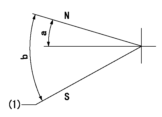
N:Pump normal
S:Stop the pump.
(1)At delivery
----------
----------
a=7.5deg+-5deg b=53deg+-5deg
----------
----------
a=7.5deg+-5deg b=53deg+-5deg
Timing setting

(1)Pump vertical direction
(2)Position of gear's standard threaded hole at No 1 cylinder's beginning of injection
(3)B.T.D.C.: aa
(4)-
----------
aa=17deg
----------
a=(50deg)
----------
aa=17deg
----------
a=(50deg)
Information:
Problems during boot up
The connections should be securely fastened.
The device drivers should be installed correctly.
The jumpers on add-in boards should be positioned correctly.
Format the hard drive and set up the monitor in the BIOS.
Ensure that the DIMM is properly installed. The DIMM may need to be reinstalled in order to ensure a good connection.
The EIDE cable from the hard drive should be properly connected.
Check if the system will start with a floppy disk.
The BIOS should be properly configured. Refer to Specifications, "Basic Input Output System".Problems after start-up
Check for loose connections. Check that all ISA/PCI cards are connected securely. Check that the DIMM is fully installed.
Check the system for overheating. Check the diagnostics indicator on the display of the front panel. Check that the chassis fan is working and that the filter is clean.
The monitor has a protected power supply that is regulated. A transient voltage in the power line or peripheral cable may cause the system to lock up. A transient voltage may cause a flashing display. The monitor may restart unexpectedly. You should exit the application if this occurs. Then, restart the application.
Check the EIDE cable from the hard drive for a proper connection.
Check if the system will start with a floppy disk.
Clean the CMOS by removing and reinstalling the battery. The battery is located on the backplane. The BIOS setup will then need to be run. Refer to Specifications, "Basic Input Output System".
The software package may need to be reinstalled.Incorrect characters are displayed or distorted
The display contrast control and the display brightness control may need to be properly adjusted. The setup functions are found in the operating system that contains the video driver.
If you use the integrated display, disconnect the chassis from the bezel. Check the connection to the display.The hard drive active indicator does not come on when the hard drive is being accessed
Check the EIDE cable connections to the drive.
Check that the BIOS setup is configured properly. The drive should be enabled.
Check the connections on the I/O board.
Restart the monitor.The power on indicator does not light
Check the power.
Check the front panel connector on the processor board.
Check the connections on the I/O board.