Information injection-pump assembly
ZEXEL
101441-9890
1014419890

Rating:
Service parts 101441-9890 INJECTION-PUMP ASSEMBLY:
1.
_
6.
COUPLING PLATE
7.
COUPLING PLATE
8.
_
9.
_
10.
NOZZLE AND HOLDER ASSY
11.
Nozzle and Holder
12.
Open Pre:MPa(Kqf/cm2)
13.
NOZZLE-HOLDER
14.
NOZZLE
15.
NOZZLE SET
Cross reference number
ZEXEL
101441-9890
1014419890
Zexel num
Bosch num
Firm num
Name
101441-9890
DPICO
INJECTION-PUMP ASSEMBLY
DC24 * Q
DC24 * Q
Calibration Data:
Adjustment conditions
Test oil
1404 Test oil ISO4113 or {SAEJ967d}
1404 Test oil ISO4113 or {SAEJ967d}
Test oil temperature
degC
40
40
45
Nozzle and nozzle holder
105780-8140
Bosch type code
EF8511/9A
Nozzle
105780-0000
Bosch type code
DN12SD12T
Nozzle holder
105780-2080
Bosch type code
EF8511/9
Opening pressure
MPa
17.2
Opening pressure
kgf/cm2
175
Injection pipe
Outer diameter - inner diameter - length (mm) mm 6-2-600
Outer diameter - inner diameter - length (mm) mm 6-2-600
Tester oil delivery pressure
kPa
157
157
157
Tester oil delivery pressure
kgf/cm2
1.6
1.6
1.6
Direction of rotation (viewed from drive side)
Left L
Left L
Injection timing adjustment
Direction of rotation (viewed from drive side)
Left L
Left L
Injection order
1-3-4-2
Pre-stroke
mm
2.25
2.2
2.3
Beginning of injection position
Drive side NO.1
Drive side NO.1
Difference between angles 1
Cal 1-3 deg. 90 89.5 90.5
Cal 1-3 deg. 90 89.5 90.5
Difference between angles 2
Cal 1-4 deg. 180 179.5 180.5
Cal 1-4 deg. 180 179.5 180.5
Difference between angles 3
Cyl.1-2 deg. 270 269.5 270.5
Cyl.1-2 deg. 270 269.5 270.5
Injection quantity adjustment
Adjusting point
A
Rack position
12.9
Pump speed
r/min
750
750
750
Average injection quantity
mm3/st.
39.3
37.7
40.9
Max. variation between cylinders
%
0
-4
4
Fixing the lever
*
Injection quantity adjustment_02
Adjusting point
B
Rack position
12
Pump speed
r/min
1200
1200
1200
Average injection quantity
mm3/st.
38.5
37.5
39.5
Max. variation between cylinders
%
0
-2.5
2.5
Basic
*
Fixing the lever
*
Injection quantity adjustment_03
Adjusting point
-
Rack position
8.8+-0.5
Pump speed
r/min
350
350
350
Average injection quantity
mm3/st.
8
6.9
9.1
Max. variation between cylinders
%
0
-14
14
Fixing the rack
*
Remarks
Adjust only variation between cylinders; adjust governor according to governor specifications.
Adjust only variation between cylinders; adjust governor according to governor specifications.
Timer adjustment
Pump speed
r/min
500+-50
Advance angle
deg.
0
0
0
Remarks
Start
Start
Timer adjustment_02
Pump speed
r/min
800
Advance angle
deg.
1
0.5
1.5
Timer adjustment_03
Pump speed
r/min
1050
Advance angle
deg.
2
1.2
2.7
Timer adjustment_04
Pump speed
r/min
1200
Advance angle
deg.
2.9
2.4
3.4
Timer adjustment_05
Pump speed
r/min
-
Advance angle
deg.
6
6
6
Remarks
Measure the actual speed, stop
Measure the actual speed, stop
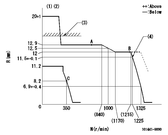
Test data Ex:
Governor adjustment

N:Pump speed
R:Rack position (mm)
(1)Target notch: K
(2)Tolerance for racks not indicated: +-0.05mm.
(3)RACK CAP: R1
(4)At delivery
----------
K=12 R1=(17.5)mm
----------
----------
K=12 R1=(17.5)mm
----------
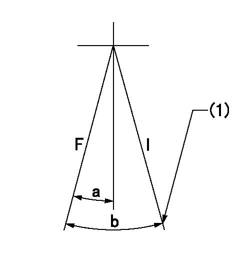
Speed control lever angle

F:Full speed
I:Idle
(1)Stopper bolt setting
----------
----------
a=9deg+-5deg b=22deg+-5deg
----------
----------
a=9deg+-5deg b=22deg+-5deg
Stop lever angle

N:Pump normal
S:Stop the pump.
(1)Normal
----------
----------
a=19deg+-5deg b=53deg+-5deg
----------
----------
a=19deg+-5deg b=53deg+-5deg
Timing setting

(1)Pump vertical direction
(2)Gear mark Z for the No. 4 cylinder's beginning of injection
(3)B.T.D.C.: aa
(4)-
----------
aa=14deg
----------
a=(60deg)
----------
aa=14deg
----------
a=(60deg)
Information:
Illustration 1 g00669441
CCM to Host Equipment Direct Connection (1) CCM (2) CCM RS-232C port (3) Computer RS-232C port (4) Host equipmentMake sure that the following equipment is available:
A personal computer. Refer to "Caterpillar CCM PC For Windows: Getting Started Manual" for specifications on the PC.
The proper RS-232C cables are required for the particular installation. Refer to the Operation and Maintenance Manual, "RS-232C Cable Requirements".
The CCM PC Software for Windows. This software is available from Caterpillar.ProcedurePerform the following procedure to initialize communication with the host equipment that is connected directly to the CCM.Note: The host equipment and the CCM should be turned OFF before you change the cables to the serial ports.
The CCM should be installed with all of the wiring. Refer to Operations and Maintenance Manual, "General Wiring Diagram" and "RS-232C Cable Requirements".
Determine the parameters for communication for the installation. The default rate of communication (bits per second or bps) is 9600. The remaining default settings from the factory are no parity, 8 data bits, and 1 stop bit. These parameters will work well in most installations. Use the Operations and Maintenance Manual, "Communication Parameters - Identify" to determine the parameters of communication that are stored in the CCM.
Load the CCM PC For Windows software into the PC. Refer to the "Caterpillar CCM PC For Windows: Getting Started Manual". Start the CCM PC program and connect to the CCM.
Go to the Data Link pull-down menu. Select ECM, CCM. Go to the CCM configuration screen in the Utilities menu. Set the parameters for communication to match the values that were chosen in step 2.
Use the CCM configuration screen to set the Connection Type to Direct Connection. The CCM is now set at the determined communication configuration.Note: If the PC is required to communicate with the CCM, go to the Phone Book pull-down menu and select Add or Edit. Set the communication parameters of the PC to the values that were chosen in Step 2.Note: The electronic controller of each engine must be programmed with the correct engine number for identification on the CCM. The electronic controller is programmed to Engine Number 1 at the factory. Refer to Operation and Maintenance Manual, SEBU6874, "Engine Number - Program".Note: After the CCM has been connected to the PC, refer to the "CCM PC Software Users Manual". This manual contains instructions on monitoring and on controlling the engine remotely.Note: Two conditions must be met before the electronic engine controller will allow control by the CCM. The Engine Control Switch must be in the AUTO position, and the remote initiate contacts must be open. The engine may be monitored with the ECS in any position.Note: For an EMCP II application, the CCM cannot control the generator set if the GSC is in Service Mode. The generator set can only be monitored.
Have questions with 101441-9890?
Group cross 101441-9890 ZEXEL
Dpico
Nissan-Diesel
Daewoo
Nissan-Diesel
Nissan-Diesel
Nissan-Diesel
Nissan-Diesel
Nissan-Diesel
Daewoo
Dpico
101441-9890
INJECTION-PUMP ASSEMBLY
DC24
DC24