Information injection-pump assembly
ZEXEL
101441-9850
1014419850
NISSAN-DIESEL
1671290177
1671290177
Rating:
Service parts 101441-9850 INJECTION-PUMP ASSEMBLY:
1.
_
6.
COUPLING PLATE
7.
COUPLING PLATE
8.
_
9.
_
11.
Nozzle and Holder
16600-43G02
12.
Open Pre:MPa(Kqf/cm2)
9.8{100}
15.
NOZZLE SET
Cross reference number
ZEXEL
101441-9850
1014419850
NISSAN-DIESEL
1671290177
1671290177
Zexel num
Bosch num
Firm num
Name
Calibration Data:
Adjustment conditions
Test oil
1404 Test oil ISO4113 or {SAEJ967d}
1404 Test oil ISO4113 or {SAEJ967d}
Test oil temperature
degC
40
40
45
Nozzle and nozzle holder
105780-8140
Bosch type code
EF8511/9A
Nozzle
105780-0000
Bosch type code
DN12SD12T
Nozzle holder
105780-2080
Bosch type code
EF8511/9
Opening pressure
MPa
17.2
Opening pressure
kgf/cm2
175
Injection pipe
Outer diameter - inner diameter - length (mm) mm 6-2-600
Outer diameter - inner diameter - length (mm) mm 6-2-600
Tester oil delivery pressure
kPa
157
157
157
Tester oil delivery pressure
kgf/cm2
1.6
1.6
1.6
Direction of rotation (viewed from drive side)
Right R
Right R
Injection timing adjustment
Direction of rotation (viewed from drive side)
Right R
Right R
Injection order
1-3-4-2
Pre-stroke
mm
2.15
2.1
2.2
Beginning of injection position
Drive side NO.1
Drive side NO.1
Difference between angles 1
Cal 1-3 deg. 90 89.5 90.5
Cal 1-3 deg. 90 89.5 90.5
Difference between angles 2
Cal 1-4 deg. 180 179.5 180.5
Cal 1-4 deg. 180 179.5 180.5
Difference between angles 3
Cyl.1-2 deg. 270 269.5 270.5
Cyl.1-2 deg. 270 269.5 270.5
Injection quantity adjustment
Adjusting point
A
Rack position
11.3
Pump speed
r/min
1500
1500
1500
Average injection quantity
mm3/st.
47
46
48
Max. variation between cylinders
%
0
-2.5
2.5
Basic
*
Fixing the lever
*
Injection quantity adjustment_02
Adjusting point
-
Rack position
8.3+-0.5
Pump speed
r/min
400
400
400
Average injection quantity
mm3/st.
8
6.9
9.1
Max. variation between cylinders
%
0
-15
15
Fixing the rack
*
Remarks
Adjust only variation between cylinders; adjust governor according to governor specifications.
Adjust only variation between cylinders; adjust governor according to governor specifications.
Timer adjustment
Pump speed
r/min
-
Advance angle
deg.
0.5
Remarks
Measure the actual speed.
Measure the actual speed.
Timer adjustment_02
Pump speed
r/min
-
Advance angle
deg.
3.5
3
4
Remarks
Measure the actual speed.
Measure the actual speed.
Timer adjustment_03
Pump speed
r/min
1800
Remarks
Measure the actual advance angle.
Measure the actual advance angle.
Timer adjustment_04
Pump speed
r/min
-
Advance angle
deg.
7.3
7.3
7.3
Remarks
Measure the actual speed, stop
Measure the actual speed, stop
Test data Ex:
Governor adjustment
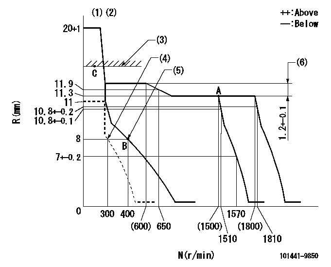
N:Pump speed
R:Rack position (mm)
(1)Target notch: K
(2)Tolerance for racks not indicated: +-0.05mm.
(3)RACK LIMIT: RAL
(4)Set idle sub-spring
(5)Main spring setting
(6)Rack difference between N = N1 and N = N2
----------
K=9 RAL=14+-0.1mm N1=1500r/min N2=550r/min
----------
----------
K=9 RAL=14+-0.1mm N1=1500r/min N2=550r/min
----------
Speed control lever angle
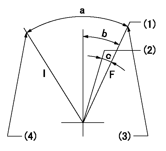
F:Full speed
I:Idle
(1)Set the pump speed at aa. ( At delivery )
(2)When pump speed set at bb
(3)Stopper bolt setting
(4)Stopper bolt setting
----------
aa=1810r/min bb=1510r/min
----------
a=32deg+-5deg b=20deg+-5deg c=8deg+-5deg
----------
aa=1810r/min bb=1510r/min
----------
a=32deg+-5deg b=20deg+-5deg c=8deg+-5deg
Stop lever angle
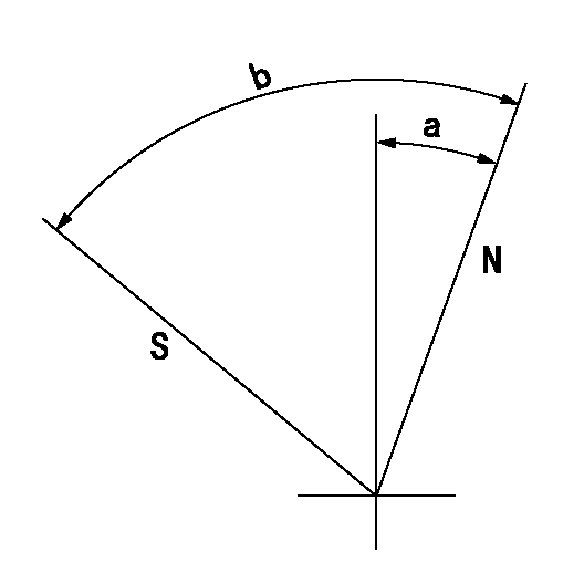
N:Pump normal
S:Stop the pump.
----------
----------
a=12deg+-5deg b=53deg+-5deg
----------
----------
a=12deg+-5deg b=53deg+-5deg
0000001501 GOV FULL LOAD ADJUSTMENT
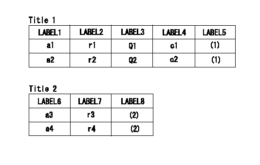
Title1:Full load stopper adjustment
Title2:Governor set speed
LABEL1:Distinguishing
LABEL2:Pump speed (r/min)
LABEL3:Ave. injection quantity (mm3/st)
LABEL4:Max. var. bet. cyl.
LABEL5:Remarks
LABEL6:Distinguishing
LABEL7:Governor set speed (r/min)
LABEL8:Remarks
(1)Adjustment conditions are the same as those for measuring injection quantity.
(2)-
----------
----------
a1=A a2=- r1=1500r/min r2=- Q1=47+-1mm3/st Q2=- c1=+-2.5 % c2=- a3=36 a4=30 r3=1800r/min r4=1500r/min
----------
----------
a1=A a2=- r1=1500r/min r2=- Q1=47+-1mm3/st Q2=- c1=+-2.5 % c2=- a3=36 a4=30 r3=1800r/min r4=1500r/min
Timing setting

(1)Pump vertical direction
(2)Position of gear mark 'ZZ' at No 1 cylinder's beginning of injection
(3)B.T.D.C.: aa
(4)-
----------
aa=16deg
----------
a=(100deg)
----------
aa=16deg
----------
a=(100deg)
Information:
Environmental
The ambient operating temperature range is from -40° to 70°C (-40° to 158°F).
The storage temperature is from -40° to 85°C (-40° to 185°F).
The unit must be protected from direct contact with liquids. If sealing of the unit is required, the CCM must be in a water tight enclosure.
The CCM weighs 0.75 kg (1.65 lb).Mounting
The CCM can be located on a desk or on a shelf. The rubber feet on the bottom of the CCM can be removed for mounting to a panel.Note: Do not mount the CCM on the engine or within the engine mounted instrument panel. The CCM is not designed for direct engine mounting.Internal Battery
The CCM contains a battery that supplies power for internal memory whenever the CCM is turned off. Refer to the Operation and Maintenance Manual, "Battery - Replace".Power Supply
The requirements for battery voltage are 15 to 45 volts DC (24 or 32 volts DC nominal power).
The +/-B power dissipation is approximately 3.0 watts at 24 volts.
The current drawn by the CCM is 0.11 amps at 12 volts and 0.13 amps at 36 volts.
Multiple engines must share a common ground (-B).
Multiple engines must use diodes to prevent power sharing between units.Dimensions
Illustration 1 g00647099
Table 1
CCM MOUNTING DIMENSIONS
Item Dimension
A
3.5 mm (0.14 in)
B
106.5 mm (4.19 in)
C
73.0 mm (2.87 in)
D
7.5 mm (0.29 in) diameter holes (4)
E
130 mm (5.12 in)
F
149.0 mm (5.87 in)
G
66.2 mm (2.61 in)
H
125.5 mm (4.94 in)
I
17.8 mm (.70 in)
