Information injection-pump assembly
ZEXEL
101441-9841
1014419841
Rating:
Service parts 101441-9841 INJECTION-PUMP ASSEMBLY:
1.
_
6.
COUPLING PLATE
7.
COUPLING PLATE
8.
_
9.
_
11.
Nozzle and Holder
16600-43G02
12.
Open Pre:MPa(Kqf/cm2)
9.8{100}
15.
NOZZLE SET
Cross reference number
ZEXEL
101441-9841
1014419841
Zexel num
Bosch num
Firm num
Name
101441-9841
INJECTION-PUMP ASSEMBLY
Calibration Data:
Adjustment conditions
Test oil
1404 Test oil ISO4113 or {SAEJ967d}
1404 Test oil ISO4113 or {SAEJ967d}
Test oil temperature
degC
40
40
45
Nozzle and nozzle holder
105780-8140
Bosch type code
EF8511/9A
Nozzle
105780-0000
Bosch type code
DN12SD12T
Nozzle holder
105780-2080
Bosch type code
EF8511/9
Opening pressure
MPa
17.2
Opening pressure
kgf/cm2
175
Injection pipe
Outer diameter - inner diameter - length (mm) mm 6-2-600
Outer diameter - inner diameter - length (mm) mm 6-2-600
Tester oil delivery pressure
kPa
157
157
157
Tester oil delivery pressure
kgf/cm2
1.6
1.6
1.6
Direction of rotation (viewed from drive side)
Right R
Right R
Injection timing adjustment
Direction of rotation (viewed from drive side)
Right R
Right R
Injection order
1-3-4-2
Pre-stroke
mm
2.15
2.1
2.2
Beginning of injection position
Drive side NO.1
Drive side NO.1
Difference between angles 1
Cal 1-3 deg. 90 89.5 90.5
Cal 1-3 deg. 90 89.5 90.5
Difference between angles 2
Cal 1-4 deg. 180 179.5 180.5
Cal 1-4 deg. 180 179.5 180.5
Difference between angles 3
Cyl.1-2 deg. 270 269.5 270.5
Cyl.1-2 deg. 270 269.5 270.5
Injection quantity adjustment
Adjusting point
A
Rack position
12.7
Pump speed
r/min
750
750
750
Average injection quantity
mm3/st.
51
50
52
Max. variation between cylinders
%
0
-2.5
2.5
Basic
*
Fixing the lever
*
Injection quantity adjustment_02
Adjusting point
-
Rack position
8.8+-0.5
Pump speed
r/min
300
300
300
Average injection quantity
mm3/st.
8
6.9
9.1
Max. variation between cylinders
%
0
-15
15
Fixing the rack
*
Remarks
Adjust only variation between cylinders; adjust governor according to governor specifications.
Adjust only variation between cylinders; adjust governor according to governor specifications.
Timer adjustment
Pump speed
r/min
(N1+50)-
-
Advance angle
deg.
0
0
0
Remarks
Start
Start
Timer adjustment_02
Pump speed
r/min
N1
Advance angle
deg.
0.5
Remarks
Measure the actual speed.
Measure the actual speed.
Timer adjustment_03
Pump speed
r/min
900
Remarks
Measure the actual advance angle.
Measure the actual advance angle.
Timer adjustment_04
Pump speed
r/min
-
Advance angle
deg.
7.3
7.3
7.3
Remarks
Measure the actual speed, stop
Measure the actual speed, stop
Test data Ex:
Governor adjustment
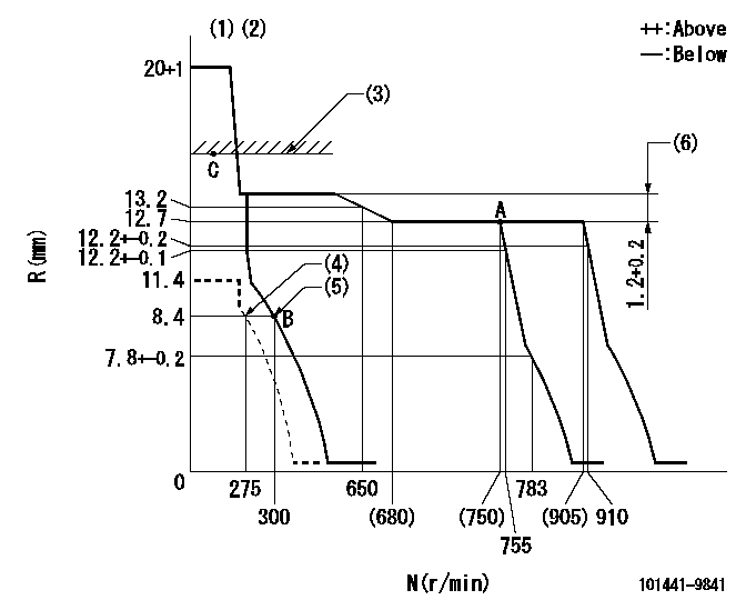
N:Pump speed
R:Rack position (mm)
(1)Target notch: K
(2)Tolerance for racks not indicated: +-0.05mm.
(3)RACK LIMIT: RAL
(4)Set idle sub-spring
(5)Main spring setting
(6)Rack difference between N = N1 and N = N2
----------
K=7 RAL=14.2+-0.1mm N1=750r/min N2=400r/min
----------
----------
K=7 RAL=14.2+-0.1mm N1=750r/min N2=400r/min
----------
Speed control lever angle
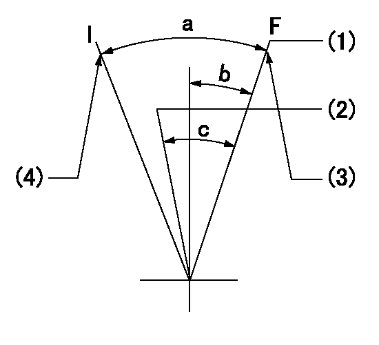
F:Full speed
I:Idle
(1)Set the pump speed at aa. ( At delivery )
(2)When pump speed set at bb
(3)Stopper bolt setting
(4)Stopper bolt setting
----------
aa=910r/min bb=755r/min
----------
a=24deg+-5deg b=0deg+-5deg c=6deg+-5deg
----------
aa=910r/min bb=755r/min
----------
a=24deg+-5deg b=0deg+-5deg c=6deg+-5deg
Stop lever angle
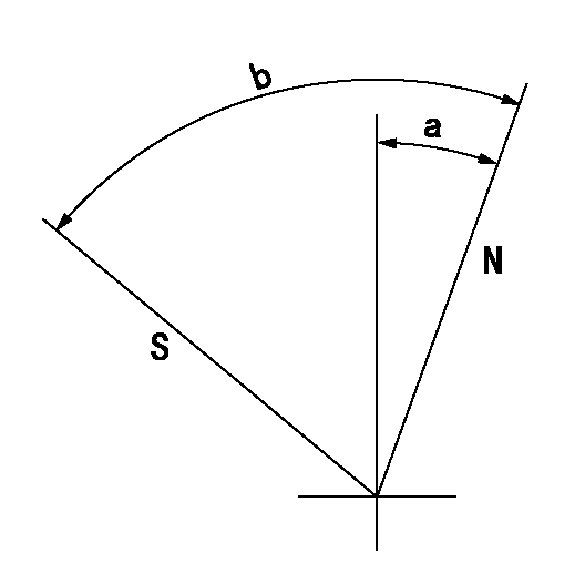
N:Pump normal
S:Stop the pump.
----------
----------
a=12deg+-5deg b=53deg+-5deg
----------
----------
a=12deg+-5deg b=53deg+-5deg
0000001501 GOV FULL LOAD ADJUSTMENT
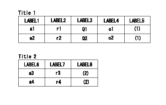
Title1:Full load stopper adjustment
Title2:Governor set speed
LABEL1:Distinguishing
LABEL2:Pump speed (r/min)
LABEL3:Ave. injection quantity (mm3/st)
LABEL4:Max. var. bet. cyl.
LABEL5:Remarks
LABEL6:Distinguishing
LABEL7:Governor set speed (r/min)
LABEL8:Remarks
(1)Adjustment conditions are the same as those for measuring injection quantity.
(2)-
----------
----------
a1=A a2=B r1=750r/min r2=750r/min Q1=51+-1mm3/st Q2=- c1=+-2.5% c2=+-2.5% a3=18 a4=15 r3=900r/min r4=750r/min
----------
----------
a1=A a2=B r1=750r/min r2=750r/min Q1=51+-1mm3/st Q2=- c1=+-2.5% c2=+-2.5% a3=18 a4=15 r3=900r/min r4=750r/min
Timing setting

(1)Pump vertical direction
(2)Position of gear mark 'ZZ' at No 1 cylinder's beginning of injection
(3)B.T.D.C.: aa
(4)-
----------
aa=16deg
----------
a=(100deg)
----------
aa=16deg
----------
a=(100deg)
Information:
Version C of the ADEM II controller (ECM) has a primary data link for use with the CCM. This data link is called the CAT Data Link. The Module Identifier (MID) of this controller is a fixed value. Each controller on the CAT Data Link must have a unique MID. The CCM can only be connected to one Version C ECM on the CAT Data Link.
Version D of the ADEM II controller (ECM) also has a primary data link for use with the CCM. The value of the MID for the primary data link is fixed. Version D also has a secondary data link for use with the CCM. The Secondary CAT Data Link has a programmable MID. A maximum of eight different values is available for generator set applications. A maximum of three different values is available for marine applications.
EMCP II (basic model) has a primary data link for use with the CCM. This data link is called the CAT Data Link. The CAT Data Link has a programmable MID. A maximum of eight different values may be used for the MID.
EMCP II+ has the same primary data link as EMCP II (CAT Data Link) with a programmable value for the MID. The EMCP II+ also has a secondary data link for use with the CCM. The CCM Data Link has a programmable value for the MID. The CAT Data Link and the CCM Data Link have eight MID values.
The Secondary CAT Data Link and the CCM Data Link can be treated in the same manner on the 3500B Version D and the EMCP II+ applications.
There is a maximum of one CCM per data link.
There is a maximum of one CCM per engine.The previous descriptions govern the connections between the devices and the CCM. When an ADEM II controller and an EMCP II or EMCP II+ controller are connected, the CAT Data Link is always used for the connections. All subsequent connections to the CCM (ADEM II Version D or EMCP II+) are made by using the secondary data link. The following examples will illustrate some valid CCM connections with multiple electronic controllers. These examples are only a representation of most possible valid connections or combinations.
Illustration 1 g00649118
MUI Generator sets with EMCP II (Basic Model)
Illustration 2 g00649133
MUI Generator sets with EMCP II+
Illustration 3 g00649182
3500B EUI Generator set (Version C ECM)
Illustration 4 g00649184
3500 B EUI Generator sets (Version D ECM)
Illustration 5 g00649192
3500B EUI Generator sets (Version C and D ECM's)For the application that is shown in Illustration 5, only one Version C ECM is allowed.
Illustration 6 g00649200
3500B EUI Generator set (Version C ECM) with EMCP II (Basic Model)
Illustration 7 g00649317
EMCP II Basic and 3500B EUI Generator set (Version D ECM)One CCM is required for each engine with Version D ECM.
Illustration 8 g00649214
3500B EUI Generator sets (Version C ECM) with EMCP II+
Illustration 9 g00649236
3500B EUI Generator sets (Version D ECM) with EMCP II+
Illustration 10 g00649243
3500B EUI Generator sets (Version D ECM) with EMCP II+A maximum of four generator sets can be connected in the application that is shown in
Have questions with 101441-9841?
Group cross 101441-9841 ZEXEL
Dpico
Nissan-Diesel
Daewoo
Nissan-Diesel
101441-9841
INJECTION-PUMP ASSEMBLY
