Information injection-pump assembly
ZEXEL
101441-9780
1014419780
Rating:
Service parts 101441-9780 INJECTION-PUMP ASSEMBLY:
1.
_
6.
COUPLING PLATE
7.
COUPLING PLATE
8.
_
9.
_
11.
Nozzle and Holder
16600-43G02
12.
Open Pre:MPa(Kqf/cm2)
9.8{100}
15.
NOZZLE SET
Cross reference number
ZEXEL
101441-9780
1014419780
Zexel num
Bosch num
Firm num
Name
101441-9780
INJECTION-PUMP ASSEMBLY
Calibration Data:
Adjustment conditions
Test oil
1404 Test oil ISO4113 or {SAEJ967d}
1404 Test oil ISO4113 or {SAEJ967d}
Test oil temperature
degC
40
40
45
Nozzle and nozzle holder
105780-8140
Bosch type code
EF8511/9A
Nozzle
105780-0000
Bosch type code
DN12SD12T
Nozzle holder
105780-2080
Bosch type code
EF8511/9
Opening pressure
MPa
17.2
Opening pressure
kgf/cm2
175
Injection pipe
Outer diameter - inner diameter - length (mm) mm 6-2-600
Outer diameter - inner diameter - length (mm) mm 6-2-600
Tester oil delivery pressure
kPa
157
157
157
Tester oil delivery pressure
kgf/cm2
1.6
1.6
1.6
Direction of rotation (viewed from drive side)
Right R
Right R
Injection timing adjustment
Direction of rotation (viewed from drive side)
Right R
Right R
Injection order
1-3-4-2
Pre-stroke
mm
2.3
2.25
2.35
Beginning of injection position
Drive side NO.1
Drive side NO.1
Difference between angles 1
Cal 1-3 deg. 90 89.5 90.5
Cal 1-3 deg. 90 89.5 90.5
Difference between angles 2
Cal 1-4 deg. 180 179.5 180.5
Cal 1-4 deg. 180 179.5 180.5
Difference between angles 3
Cyl.1-2 deg. 270 269.5 270.5
Cyl.1-2 deg. 270 269.5 270.5
Injection quantity adjustment
Adjusting point
A
Rack position
11
Pump speed
r/min
1000
1000
1000
Average injection quantity
mm3/st.
32.8
31.8
33.8
Max. variation between cylinders
%
0
-4
4
Basic
*
Fixing the lever
*
Injection quantity adjustment_02
Adjusting point
-
Rack position
8+-0.5
Pump speed
r/min
500
500
500
Average injection quantity
mm3/st.
9.5
8.4
10.6
Max. variation between cylinders
%
0
-10
10
Fixing the rack
*
Remarks
Adjust only variation between cylinders; adjust governor according to governor specifications.
Adjust only variation between cylinders; adjust governor according to governor specifications.
Injection quantity adjustment_03
Adjusting point
C
Rack position
-
Pump speed
r/min
100
100
100
Average injection quantity
mm3/st.
52
47
57
Fixing the lever
*
Rack limit
*
Timer adjustment
Pump speed
r/min
-
Advance angle
deg.
0.5
Remarks
Measure the actual speed.
Measure the actual speed.
Timer adjustment_02
Pump speed
r/min
1100
Remarks
Measure the actual advance angle.
Measure the actual advance angle.
Timer adjustment_03
Pump speed
r/min
-
Advance angle
deg.
3
3
3
Remarks
Measure the actual speed, stop
Measure the actual speed, stop
Test data Ex:
Governor adjustment
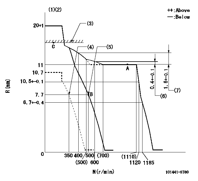
N:Pump speed
R:Rack position (mm)
(1)Target notch: K
(2)Tolerance for racks not indicated: +-0.05mm.
(3)RACK LIMIT
(4)Set idle sub-spring
(5)Main spring setting
(6)Rack difference from N = N1
(7)Rack difference to N = N2
----------
K=15 N1=1000r/min N2=1000r/min
----------
----------
K=15 N1=1000r/min N2=1000r/min
----------
Speed control lever angle
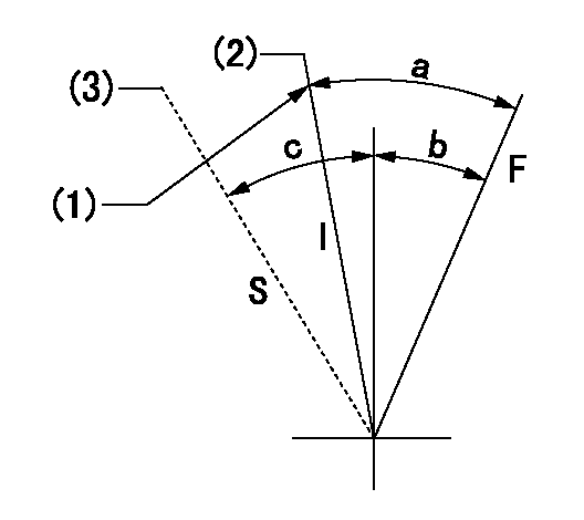
F:Full speed
I:Idle
S:Stop
(1)Stopper bolt setting
(2)At delivery
(3)Confirmation
----------
----------
a=17deg+-5deg b=5deg+-5deg c=32deg+-3deg
----------
----------
a=17deg+-5deg b=5deg+-5deg c=32deg+-3deg
Stop lever angle
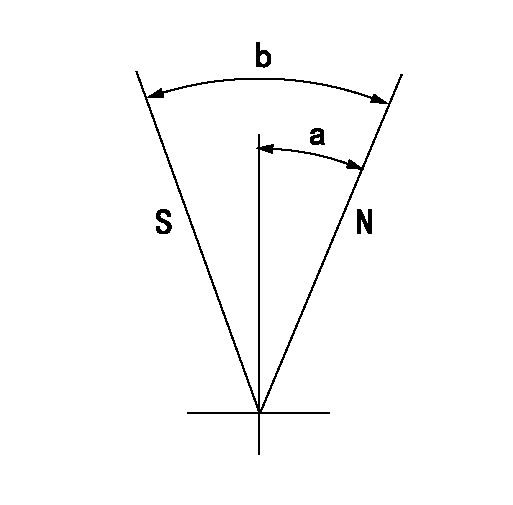
N:Pump normal
S:Stop the pump.
----------
----------
a=12deg+-5deg b=53deg+-5deg
----------
----------
a=12deg+-5deg b=53deg+-5deg
Timing setting

(1)Pump vertical direction
(2)Position of gear mark 'ZZ' at No 1 cylinder's beginning of injection
(3)B.T.D.C.: aa
(4)-
----------
aa=18deg
----------
a=(100deg)
----------
aa=18deg
----------
a=(100deg)
Information:
Illustration 1 g00596626
(1) Potentiometer (2) Light Emitting Diode (3) The Normally Closed Contact (4) Common Contact (5) Normally Open Contact
Preset the variable voltage power supply to 22 VDC.
Secure the variable voltage power supply.
Use the 4P-4029 Adjustment Tool to turn the potentiometer for the low voltage alarm module counterclockwise. Turn the potentiometer 25 times.
Remove the wire from the low voltage alarm module's positive terminal. Remove the wire from the low voltage alarm module's negative terminal.
Connect the power supply's positive lead to the low voltage alarm module's positive terminal.
Connect the power supply's negative lead to the low voltage alarm module's negative terminal.
Connect the multimeter to the N.O. contact and connect the multimeter to the COM contact. Set the multimeter to the function for measuring ohms. The multimeter should read "OL".
Energize the power supply.
Verify that the voltage is 22 VDC.
If the voltage is not 22 VDC, adjust the power supply.
Slowly turn the potentiometer for the low voltage alarm module clockwise until the LED illuminates.Note: The relay will energize after the LED illuminates. This occurs in 50 15 seconds.
Observe the multimeter in order to verify that the relay energized. The resistance reading should be low when the relay is energized.
Increase the output of the power supply to 24 VDC.Note: The LED and the relay de-energize simultaneously.
Remove the power supply's negative lead from the low voltage alarm module.
Remove the power supply's positive lead from the low voltage alarm module.
Remove the multimeter's leads from the low voltage alarm module.
Connect the system's wire to the low voltage alarm module's positive terminal. Connect the system's wire to the low voltage alarm module's negative terminal.
Have questions with 101441-9780?
Group cross 101441-9780 ZEXEL
Nissan-Diesel
Nissan-Diesel
Nissan-Diesel
Daewoo
Nissan-Diesel
Daewoo
Nissan-Diesel
101441-9780
INJECTION-PUMP ASSEMBLY
